
Manual

6
Rev. 3
Introduction
Model 136 Rear Panel Layout
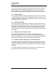
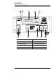
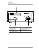
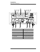
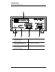
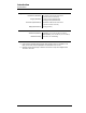
1.5 Model 136 Rear Panel Layout
1
Optional RS-232 or GPIB
communications port
(RS-232 shown)
4
Controller output receptacle
2
Auxiliary DB-9 male connector
(see
Appendix
for pinout)
5
Power cord connector
3
Sensor input DB-9 female
connector (see the
Appendix
for
the pinout diagram)
RS-232
J8
S11
ON
1
2
3
5
4