
Instruction Guide

SAFETY INFORMATION
• Read all installation instructions before beginning. If not qualified,
do not attempt installation. Contact a qualified electrician.
• To reduce the risk of fire, electric shock, or injury to persons, pay
close attention to this manual and stay within its guidelines when
using this product. Save these instructions for future use.
• This flat panel light is suitable for indoor use in dry locations only.
• Do not route the cord through walls, ceilings, doors, windows, or
any similar part of the building structure.
• Secure flat panel using only the mounting plate system provided.
• Do not secure cord with staples, nails, or like means that may
damage the outer jacket or cord insulation.
• Use only with 24V DC drivers recommended by American Lighting.
Factory warranty will be void if used with a non-recommended
power supply, transformer or driver.
• Size your 24V DC driver appropriately for your layout. Do not
exceed the maximum load of the power supply nor 96 watts total
when interconnecting multiple fixtures.
These products may represent a possible shock or fire hazard
if improperly installed or attached in any way.
Products should
be installed in accordance with these instructions, current
electrical codes, and/or the current National Electric Code (NEC).
To reduce the risk of fire, electric shock or injury to persons,
make sure that the electrical power to the system is
disconnected at the source prior to installation or any servicing.
Caution: Injury to persons and damage to the fixture and/or
mounting surface may result if the fixture is pulled from the
surface. To reduce the likelihood of such injury or damage,
mount on a surface that is mechanically sound.
Page 1 of 2©2018 American Lighting, Inc. REV1844 www.AmericanLighting.com 11775 E. 45th Ave. Denver, CO 80239 Ph: 1-800-880-1180 Fax: 303-695-7633
WARNING
WARNING
WARNING
EDGELINK FLAT PANEL (TUNABLE CCT)24V
INSTALLATION INSTRUCTIONS
EDGE-TW Series
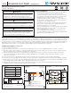
PRE-INSTALLATION (See Figures 1-3)
This product requires the use of a 24V DC driver for operation; use of the DRJ series driver (sold separately) is recommended (also compatible
with LP-DR series drivers). Do not exceed the maximum load of the power supply nor 96 watts total when interconnecting multiple fixtures. This
product requires the use of a Tunable CCT controller and receiver (Trulux Tunable CCT Controls and Receivers recommended, sold separately).
Each fixture, power connection cord, and accessory linking cable (sold separately) has dedicated, mating INPUT and OUTPUT ends and are
marked with an arrow to ensure correct orientation during installation (arrows should align when connected).
CONNECTING POWER (See Figures 1-3)
1. Turn o supply power at source.
2. Determine the total load of fixtures to be installed and use DRJ-BOX-60 for up to 60 watts or DRJ-BOX-96 for up to 96 watts. See Figure 1.
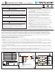
3. Determine location of driver. Lift o cover of wiring compartment and punch out the knockout most convenient for access to 120V supply wires.
They must enter the wiring compartment on the INPUT side. See Figure 2.
4. Using the metal strain relief connector provided, bring the supply wires through the knockout into the wiring compartment and make
connections matching polarity: Black to Black/Hot, White to White/Neutral and Yellow-Green striped wire (Ground) to Green or bare
copper wire. See Figure 3.
5. Punch out the knockout on the OUTPUT side that is most convenient for the receiver wires to enter the wiring compartment.
6. Connect the receiver to the DRJ driver by making connections in the wiring compartment as follows: Red(+) to Red(+) and Black(-) to Black(-).
7. Connect the 6 ft power connector wire included with the flat panel to the receiver by making connections as follows: ‘Red to WW(+) channel,
Black
to CW(+) channel, Yellow to WW(-) channel, and White to CW(-) channel. See Figure 2.
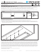
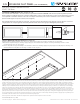
8. Attach the driver and receiver to the mounting surface with the mounting screws provided via the through holes inside the wiring
compartment and the mounting tabs at the opposite end. See Figure 3.
FIGURE 1 FIGURE 2 FIGURE 3
EdgeLink TW Panel Watts
EDGE-TW-8-WH 7
EDGE-TW-16-WH 13
EDGE-TW-22-WH 19
EDGE-TW-34-WH 24
Black
White
Yellow
Red
Black
T:80 0.880.1180 | Tec hni calSupport@AmericanLighting.com | www.AmericanL ighting.co m
Model: DRJ-BOX-96
Input: 90-132VAC (1.4A max) / 60Hz
Output: 24VDC (4.1A) Max Load: 96W
Ta: 45°C Tc: 80°C PF: ≥0.70
Suitable for use in Dry & Damp Locations
Install in accordance with the National and Local Electrical Code
Cover of wiring compartment
Through mounting holes
are under the cover
Mounting tabs
to 120V Power
to Receiver
Receiver
EdgeLink
Flat Panel
DRJ Series 24V Driver
Black
White
Yellow
Red
Black
BLACK
BLACK
RED
HOT
WHITENEUTRAL
GROUND
YELLOW & WHITE
BLACK & RED
YELLOW/GR
Trulux RF Controller
(TWRF-BATT shown)
Push ON/OFF
RF Controller “talks” to the receiver via a
wireless Radio Frequency (RF) signal
WW
CW
CW
WW
ww
red
1
cw
green
2
ww
blue
3
cw
white
4
BLACK
RED
YELLOW
WHITE