Instruction Manual MR-915C-SL Video Transmitter With Bi-directional Multi-Protocol Data And Bi-directional Contact Closure Copyright 2012, American Fibertek, Inc.
Table of Contents FUNCTIONAL DESCRIPTION ............................................................................. 3 INSTALLATION .................................................................................................... 4 DATA INPUT / OUTPUT CONNECTIONS ........................................................... 5 CHANNEL BIAS / TERMINATION SWITCHES.................................................... 6 MR-915C-SL STATUS INDICATORS...............................................................
INSTALLATION AND OPERATION INSTRUCTIONS INTRODUCTION Thank you for purchasing your American Fibertek MR-915C-SL singlemode video receiver with bidirectional multi-protocol data and bi-directional contact closure. Please take a few minutes to read these installation instructions in order to obtain the maximum performance from this product.
INSTALLATION THIS INSTALLATION SHOULD BE MADE BY A QUALIFIED SERVICE PERSON AND SHOULD CONFORM TO THE NATIONAL ELECTRICAL CODE, ANSI/NFPA 70 AND LOCAL CODES. Mount the unit to a secure surface using #8 (3mm) hardware in four places. See the drawing on the next page for mounting dimensions. Be sure to allow sufficient room for the required minimum bend radius of the fiber cable used. POWER SOURCE THIS PRODUCT SHALL BE POWERED BY A LISTED CLASS 2 POWER SUPPLY ONLY.
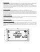
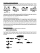
DATA INPUT / OUTPUT CONNECTIONS Data input and output connections are made via terminal blocks on the right side of the unit. See the drawings below for proper orientation of the input and output connections for Data Channel 1. Please note that the far right pin on each connection drawing corresponds with the terminal block pin located closest to the base of the unit. Follow the label on the unit for proper orientation of the input and output contact closure connections for Data Channel 2.
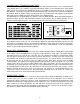
CHANNEL BIAS / TERMINATION SWITCHES Switches are available internally that allow offset bias and termination features to be activated when using RS485 data. These switches also allow termination features to be activated when using RS422 data. In order to reconfigure the RS485/422 channel, the module needs to be opened up. To open the MR-915C-SL, remove the end panel on the terminal block side and remove the screw on the bottom of the module. Slide the PCB assembly out about half way.
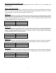
MR-915C-SL STATUS INDICATORS The MR-915C-SL receiver provides the following LED status indicators to aid in installation and troubleshooting: DATA TX/RX INDICATORS DATA TX and DATA RX indicators are provided to monitor each of the two available data channels. DATA 1 TX and RX correspond with the multi-protocol input/output of DATA CH 1. DATA 2 TX and RX correspond with the contact closure input/output of DATA CH 2.
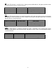
VLI A bi-color LED indicator is provided for the video input to the MR-915C-SL. DC power and video status associated with this LED is summarized below. Video Presence LED Green Red Off DC Power Status On On Off Video Status Proper Input Video Present Input Video Not Detected Check Power Supply OLI A bi-color LED indicator monitors the optical input power of the data signal that is being received at the MR-915C-SL from the MT-915C-SL or the RT-915C-SL.
LIFETIME WARRANTY INFORMATION American Fibertek, Inc warrants that at the time of delivery the products delivered will be free of defects in materials and workmanship. Defective products will be repaired or replaced at the exclusive option of American Fibertek. A Return Material Authorization (RMA) number is required to send the products back in case of return. All returns must be shipped prepaid. This warranty is void if the products have been tampered with.