Instruction Manual MR-913C-SL Video Receiver With Bi-directional Multi-Protocol Data 09/30/2012 JPK
Table of Contents Functional Description ................................................................................. 3 Installation ................................................................................................... 4 Power Source .............................................................................................. 4 Power Connection ....................................................................................... 4 Fiber Connection ......................................
INSTALLATION AND OPERATION INSTRUCTIONS INTRODUCTION Thank you for purchasing your American Fibertek MR-913C-SL singlemode video receiver with bidirectional multi-protocol data. Please take a few minutes to read these installation instructions in order to obtain the maximum performance from this product. FUNCTIONAL DESCRIPTION The MR-913C-SL operates as half of a transmitter / receiver pair for the transmission of high performance 10 bit digital NTSC, PAL, RS170, or RS343 video signals.
INSTALLATION THIS INSTALLATION SHOULD BE MADE BY A QUALIFIED SERVICE PERSON AND SHOULD CONFORM TO THE NATIONAL ELECTRICAL CODE, ANSI/NFPA 70 AND LOCAL CODES. Mount the unit to a secure surface using #8 (3mm) hardware in four places. See the drawing at the bottom of this page for mounting dimensions. Be sure to allow sufficient room for the required minimum bend radius of the fiber cable used. POWER SOURCE THIS PRODUCT SHALL BE POWERED BY A LISTED CLASS 2 POWER SUPPLY ONLY.
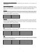
DATA INPUT / OUTPUT CONNECTIONS Data input and output connections are made via terminal blocks on the right side of the unit. See the drawings below for proper orientation of input and output connections. Please note that the far right pin on each connection drawing corresponds with the terminal block pin located closest to the base of the unit.
CHANNEL BIAS/TERMINATION SWITCHES Switches are available internally that allow offset bias and termination features to be activated when using RS485 data. These switches also allow termination features to be activated when using RS422 data. In order to reconfigure the RS485/422 channel, the module needs to be opened up. To open the MR-913C-SL, remove the end panel on the terminal block side and remove the screw on the bottom of the module. Slide the PCB assembly out about half way.
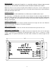
MR-913C-SL STATUS INDICATORS The MR-913C-SL transmitter provides the following LED status indicators to aid in installation and troubleshooting: DATA TX/RX INDICATORS DATA TX and DATA RX indicators are provided to monitor each of the three available data channels. DATA 1 TX and DATA 1 RX correspond with DATA CH 1 input/output. Indicators for Channel 2 and Channel 3 are also provided. An explanation follows for these DATA TX and DATA RX indicators.
SYNC A bi-color LED indicator is provided to monitor the proper serialization of the electrical data stream through the MR-913C-SL and out onto the fiber. DC power and sync status associated with this LED is summarized below.