
User's Manual


Installation 5
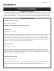
Installation
Compressor Installation
Component Installation
This section pertains to the installation of the air compressor, PTO, pump and
other related items. The instructions are intended as a guide to assist you with
particular installation. These instructions will provide only general information.
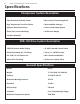
Torque and Procedure Chart
Pulsation Chamber Assembly
Torque Value: 31 FT. LBS.
Procedure: See Head Installation Procedure Section
Head Assembly
Torque Value: 31 FT. LBS.
Procedure: Assemble both heads on the cylinders with head bolts started only, not tight. Set
pulsation chamber in place between heads, making sure the “O” ring is in place in each
head. Screw the (4) chamber mounting bolts down but not tight. Snug (6) head bolts in
each head to light torque. Tighten (4) chamber bolts to 31 Ft-lbs. torque. Tighten (6) head
bolts in each head to 31 Ft-lbs. torque, doing the (2) long center bolts first and the (4) short
bolts last. After five hours of use re-torque bolts to 31 Ft-lbs.
Cylinder Assembly
Torque Value: 31 FT. LBS.
Procedure: After assembling cylinder over pistons and setting into place, tighten (6) cap
screws finger tight. In a criss-cross pattern, tighten bolts evenly so all bolts are hand snug.
Again in a criss-cr
oss patter
n tor
que each bolt to 31 Ft-lbs., checking each bolt twice. After
five hours of use, r
e-tor
que bolts to 31 Ft-lbs.
Connecting Rod Assembly
Torque Value: 18 FT. LBS.
Procedure: Assemble rod onto the crankshaft taking care to align the machined surfaces
together and tighten cap screws finger tight. Tighten bolts until hand tight and torque to 18
Ft-lbs. Check twice the torque reading before final assembly of the cylinders.