
Specifications


SPEEDDOME ULTRA PRESSURIZED OUTDOOR DOME HOUSING 8200-0462-01, REV. B
INSTALLATION AND SERVICE GUIDE
8 of 10
Reference
Wiring Color Code
Wiring Color Code for Power and Control
Inputs (outside of housing)
Power
1 Camera Power (24Vac) Black
2 Earth Ground Red
3 Camera Power (24Vac) White
Data
1 RS-422 Rx+ (SensorNet) Orange
2 RS-422 Rx– (SensorNet) Green
3 RS-422 Tx+ Yellow
4 RS-422 Tx– Brown
5 SensorNet (See Note)
6 SensorNet (See Note)
Note: The I/O circuit board wiring factory set up is
for RS-422. For SensorNet (or Manchester)
installations, disconnect orange and green wires
from P1-1 and P1-2 respectively, and reconnect
these wires to P1-5 and P1-6.
Wiring Color Code for Power and Data Inputs
(on I/O circuit board)
1
P1
P4
P3
P8
P7
JW1
I/O BOARD
JW1 Terminations
FUNCTION
Terminated
Unterminated
PINS
1-2
2-3
Pin 1
Pin 1
Pin 1
Pin 1
Power (Euro Style Connector P7)
1 Camera Power (24Vac) Black
2 Earth Ground Red
3 Camera Power (24Vac) White
Control (Euro Style Connector P1)
1 RS-422 Rx+ (SensorNet) Orange
2 RS-422 Rx– (SensorNet) Green
3 RS-422 Tx+ Yellow
4 RS-422 Tx– Brown
5 SensorNet/Manchester+ Orange
6 SensorNet/Manchester– Green
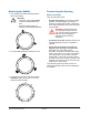
Wiring Color Code for Power and Control
Inputs (on pressure sensor circuit board)
Note: This board is not accessible to the installer.
It is between the housing and the fan/heater
brackets.
Power and Control Leads
1 Camera Power
(earth ground)
Red
2 Camera Power (24Vac) White
3 Accessory Power (24Vac) Black
4 RS-422 Rx+ (SensorNet) Orange
5 RS-422 Rx– (SensorNet) Green
6 RS-422 Tx+ Yellow
7 RS-422 Tx– Brown
8 Low Pressure Alarm White/Black
9 Low Pressure Alarm White/Red