
Installation guide


SPEEDDOME ULTRA OUTDOOR HOUSING 8200-0184-10, REV. C
CONTINUATION OF INSTALLATION GUIDE
9 of 12
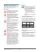
Troubleshooting
This section covers what to do when:
• Dome does not respond to commands
• Fans do not turn
• Picture is grainy or discolored
• Poor video
• Ice forms on bubble.
Dome Does Not Respond to Commands
Follow steps until the problem is corrected. See
page 5 to order parts.
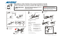
1. Detach the camera dome from the base and
check the address switches. Are they set
correctly?
- YES: Continue.
- NO: Set the correct address and reconnect
the dome.
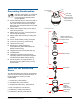
2. Verify power is reaching the housing. Press and
hold switch SW2 on the environmental PC
board and observe the green (ac power) LED.
Does the LED glow steadily?
- YES: Reattach the dome and continue.
- NO: Check power at the J-box and ac cable
connections at connector P7 on the other
side of the environmental PC board. If OK,
replace the PC board.
Connector P7 pin outs
Pin Color Description
1 N/A 24Vac
2 N/A EMI Ground
3 N/A 24Vac
CAUTION: Use a 2.5mm (0.1in) slotted
screwdriver. Using a blade too wide can
damage connectors.
CAUTION: Screws on the ac connector are
delicate. DO NOT over tighten them!
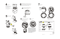
3. Verify data is reaching the housing.
SENSORNET or RS-422: Press and hold switch
SW2 on the environmental PC board and
observe the yellow (comm.) LED. The LED
should blink (SensorNet) or glow steadily
(RS-422).
To verify RS-422 connections at connector P1,
press and hold data test switch SW1 on
environmental PC board. Check the nearby red
and green LEDs; they indicate the following:
Constant green,
Blinking red
RS-422 line is correctly
wired.
Constant green,
No red
RS-422 “Data In –” is
shorted to circuit ground.
Constant red,
Blinking green
“Data In + /–” wires are
reversed.
Blinking red,
Green off
“Data In +” is shorted to
circuit ground.
Both LEDs off “Data In +/–” wires are
shorted or open.
P1 pin outs:
Manchester data connections (Ultra IV only)
Pin Color Designation
1-4 — Not used.
5 Black Manchester (+)
6 White Manchester (–)
RS-422 Data connections
Pin Color Designation
1 Orange RS-422 Data In High (+)
2 Green RS-422 Data In Low (–)
3 Yellow RS-422 Data Out High (+)
4 Brown RS-422 Data Out Low (–)
5-6 — Not used.