
Installation guide


4
6
5
A
B
C
B
A
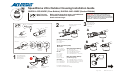
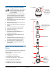
ttach bubble to housing.
V
andal-resistant version has
additional shield installed.
Remove and discard
both eyeball covers.
Set the dome
address.
Turn clockwise
to lock.
Connect dome camera by aligning
protrusion on dome with protrusion
on the mounting base (-01
housing), or white mark on PC
board (-02 housing).
IMPORTANT! Both the outdoor housing and dome
camera are shipped “terminated” for when they
are installed at the end of a data cable. Should the
cable continue to another dome, “unterminate”
the housing. See information attached.
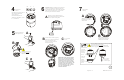
To avoid motor damage,
turn eyeball to
expose second cover!
slowly
C
7
A
ttach bubble
assembly.
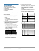
A
A
ttach lanyard to stud on
flange of housing. Secure
with thumbnut.
B
A
Remove lining from adhesive-backed
desiccant bag and affix bag,
to top of mounting base.
adhesive side
down,
8200-0184-10, Rev. CPage 2 of 12
IMPORTANT! Power the dome (heater
fans turn on) and check it performs its
homing routine. During this routine, the
camera lens moves up into the dome
housing, down to the floor, pans slowly,
and moves up to its home position. The
controller can then be used to call up
and control the dome. If OK, continue.
If not, see “Troubleshooting” in
information attached.
Ensure all four
tamperproof
screws are tight.
Sunshield
Once the bubble is attached to the housing, surface A
must meet surface B .
Ensure lanyard is not caught between flange
and trim ring gasket, or trim ring and sunshield.
on all sides
Check for
cracks in
bubble.
Discard
bubble if
found.
Check for
bent flange.
Discard
housing if
found.
A
B
7
1
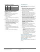
SW3 SW2 SW1
x100 x10 x1
The address range is from 001 to
255, except for Manchester,
which is 01 to 64.
Set switches. Example: For
address 107, set SW3 to 1, SW2
to •, and SW1 to 7.