
Installation guide


SPEEDDOME ULTRA OUTDOOR HOUSING 8200-0184-10, REV. C
CONTINUATION OF INSTALLATION GUIDE
11 of 12
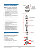
Ice Forms on Bubble
Follow steps until the problem is corrected. See
page 5 to order parts.
1. Are fans in the housing are working? If not, see
“Fans Do Not Turn” opposite.
2. Is the camera dome receiving power? Look for
evidence such as a picture on the video monitor
or dome movement.
3. Detach the dome to access the environmental
PC board.
Note: Power to the heater comes from the
dome. The heater will not function with the
dome removed.
CAUTION: Touch the metal housing before
handling the PC board.
4. Verify power is reaching the housing. Press and
hold switch SW2 and observe the green (ac
power) LED; it should glow steadily. If not,
check power at the J-box and if the ac cable is
plugged into connector P7 on other side of
environmental PC board.
CAUTION: Use a 2.5mm (0.1in) slotted
screwdriver. Using a blade too wide can
damage connectors.
CAUTION: Screws on the ac connector are
delicate. DO NOT over tighten them!
5. Check the heater connector on other side of the
environmental PC board. Is it plugged into
connector P2?
- YES: Unplug the heater cable and check
heater resistance across pins of plug. Is the
resistance approximately 16 ohms?
If yes, replace environmental PC board
0301-0949-01. If not, replace fan/heater
assembly 0400-0935-01 by removing the two
screws.
- NO: Plug the connector in, reinstall the
environmental PC board, and reattach the
dome. If the fans still do not work, replace
the fan/heater assembly.
Specifications
Electrical (combined dome and housing)
Input Voltage .............................. 24 to 30Vac, 50/60 Hz
UL Listed Class 2
Certified Limited Power Source
Design Tolerance ....................... 20 to 36Vac, 50/60 Hz
Power Consumption ................... 80W max.
Power On In-Rush current.......... 3A
Surge Protection:
Video .......................................... Series resistor of 3.9 ohms;
low-capacitance Zener
suppressor of 6.5V, 1500W,
500W, 10kA impulse-rated gas
tube
Power Line.................................. TVS rated at 60V, 1.5 joules,
250A 8/20µs impulse, 500W,
10kA impulse-rated gas tube
RS-422 ....................................... Series resistor of 3.3 ohms;
TVS rated at 5.6V, 40A, 0.1
joules, 8/20µs impulse, 500W,
10kA impulse-rated gas tube
Manchester/SensorNet............... Isolation transformer coupled
2000Vrms; PTC fuse protects
transformer; TVS rated at
5.6V, 40A, 0.1 joules, 8/20µs
impulse, 500W, 10kA impulse-
rated gas tube
Alarm Input ................................. Series resistors of 33 ohms;
TVS rated at 5.6V, 40A, 0.1
joules, 8/20µs impulse, 500W,
10kA impulse-rated gas tube
Auxiliary Output .......................... 1000V Isolation Form 1-C
relay
Environmental
Operating Temperature .............. –40°C to 50°C
(–40°F to 122°F)
Relative Humidity........................ 0 to 95% non-condensing
Storage Temperature ................. –10°C to 50°C
(–14°F to 122°F)
Wind loading............................... Sustained winds of
240Km/hour (150 miles/hour)
when properly installed and
mounted (wall, pole, ceiling,
and over-the-roof mount with
proper support)
Mechanical
Height ......................................... 32.1cm (12.6in)
Diameter ..................................... 24.4cm (9.6in)
Weight:
Without dome ............................. 2.7kg (6.1 lbs.)
With dome .................................. 3.9kg (8.7 lbs.)
Mechanical connection............... 1.5in NPT