
Installation guide


SENSORRAIL IIIE ADRL3TRK SERIES 8200-0593-02, REV. A
INSTALLATION GUIDE
3 of 34
Before You Begin
IMPORTANT! Proper installation requires:
• Observing safety guidelines
• Analyzing the ceiling structure along the
proposed rail route
• Considering space needed to service the rail
• Considering space needed to install the
PowerRail module
• Considering distance to nearby lights to prevent
them from silhouetting the camera location
• Determining the location of ceiling suspension
assembly components, such as M8 threaded
rods and anti-sway cables
• Knowing parts supplied, parts to be purchased,
and tools and equipment required
• Understanding the installation process by
reading procedures in this guide in detail before
beginning installation.
Safety Guidelines
The rail system must conform with all applicable
Standards or Codes of Practice pertaining to the
country or state in which it is to be installed.
Specifically:
• Certified electricians (in accordance with local
regulations) must be used to install mains power
cabling and termination.
• Licensed machinery operators must be used
during installation of the system.
• A dedicated power circuit equipped with a 6A
breaker and 30mA differential must be allocated
to the system.
• Exposed and external cables must be placed in
conduit or sheathed in cable wrap.
Ceiling Irregularities
CAUTION: DO NOT mount the rail
directly to the ceiling. Irregular ceilings
can distort the rail and damage it as the
ceiling expands and contracts.
A Hilti MF C31/8 fast grip system and Hilti MQ-41
suspension bar (not supplied) may be required to
attach the rail to ceiling red iron.
Acoustic Tile Ceilings
WARNING! DO NOT mount the rail
structure directly to an acoustic tile
ceiling; it cannot support the weight.
Instead, extend threaded rods through
the tile to a rigid ceiling structure capable
of supporting the weight.
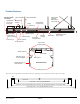
Space Requirements
Allow at least:
• 60cm (24in) from the ends of the rail to vertical
surfaces, such as walls to enable the camera
trolley to be removed and serviced.
• 50cm (20in) of vertical space above the rail to
install the PowerRail module.
• 23cm (9in) from the rail to nearby lights
- Because lights can silhouette the dome
camera, making it visible to people below the
rail, factor in the installation height of the rail
to nearby lighting.
- Ensure the gap between the rail and the
lighting system is no more than 5cm (2in) to
reduce artifacts inside the cowling.
IMPORTANT! Installing the rail
perpendicular to a tube-type lighting system
may cause more artifacts than when it is
installed in parallel.
Lay Out the Structure on the Ground
Lay out the rail system on a piece of paper to
identify ceiling obstacles along the route, lighting
that can affect covert operation, and where to place
the anti-sway cables.
Anti-Sway Cable Locations
To prevent the rail from swaying, two anti-sway
cables angled out no more than 35° from vertical
are installed at each end of the rail. Additionally:
• For rails 9.1m (30ft) or less, one crisscrossed
anti-sway cable is installed at the center of the
rail.
• For rails 9.1m (30ft) or more, anti-sway
crisscrossed cables are installed vertical to the
rail every 15m (49.2ft) as required.
• If the last two crisscrossed anti-sway cables
cannot be separated by 15m (49.2ft), then
reduce spacing between all crisscrossed cables
to make them equidistant.