
Technical data


Guide Specifications—For Liebert DataMate 1.5- to 3-Ton (5 to 10.5kW)
33 Liebert
®
DataMate
™
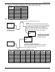
2.1.3 Microprocessor Control System
The control system shall be microprocessor-based, factory-wired into the system and tested prior to
shipment. The wall-mounted control enclosure shall include a 2-line by 16-character LCD providing
continuous display of operating status and alarm condition. An 8-key membrane keypad for setpoint/
program control, fan speed selection and unit On/Off shall be located below the display. The control
display shall be field-wired to the control board using 4-conductor field-supplied thermostat wire.
Temperature and humidity sensors shall be located in the wall box, which shall be capable of being
located up to 300 ft (91.4m) from the evaporator unit.
2.1.3.1 Monitoring
The LCD shall provide On/Off indication, operating mode indication (cooling, heating, humidifying,
dehumidifying), fan speed indication and current day, time, temperature and humidity (if applicable)
indication. The monitoring system shall be capable of relaying unit operating parameters and alarms
to the Liebert SiteScan
®
monitoring system.
2.1.3.2 Control Setpoint Parameters
• Temperature Setpoint: 65-85°F (18 to 29°C)
• Temperature Sensitivity: 1 to 9.9°F (1 to 5°C)
• Humidity Setpoint: 20-80% RH
• Humidity Sensitivity: 1 to 30% RH
The microprocessor can be set within these ranges; however, the unit may not be able to control to
extreme combinations of temperature and humidity.
2.1.3.3 Unit Controls
2.1.3.3.1 Compressor Short-Cycle Control
The control system shall prevent compressor short-cycling by a 3-minute timer from compressor stop
to the next start.
2.1.3.3.2 Common Alarm and Remote On/Off
A common alarm relay shall provide a contact closure to a remote alarm device. Two (2) terminals
shall also be provided for remote On/Off control. Individual alarms shall be “enabled” or “disabled”
from reporting to the common alarm.
2.1.3.3.3 Setback Control
The control shall be user-configurable to use a manual setpoint control or a programmable, time-
based setback control. The setback control will be based on a 5 day/2 day programmed weekly
schedule with capability of accepting 2 events per program day.
2.1.3.3.4 Temperature Calibration
The control shall include the capabilities to calibrate the temperature and humidity sensors and
adjust the sensor response delay time from 10 to 90 seconds. The control shall be capable of displaying
temperature values in °F or °C.
2.1.3.3.5 System Auto Restart
For startup after power failure, the system shall provide automatic restart with a programmable (up
to 9.9 minutes in 6-second increments) time delay. Programming can be performed either at the
wall-mounted controller or from the central, site-monitoring system.