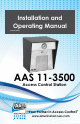
Installation and Operating Manual (version 4.05) AAS 11-3500 Access Control Station “Your Partner in Access Control” www.americanaccess.
Contents PARTS CHECKLIST4 INTRODUCTION SETTING THE SYSTEM (FACILITY) CODE PROGRAMMING THE 11-3500 VALIDATING A SINGLE CARD. VALIDATING A BLOCK OF CARDS. VOIDING CARDS. SETTING THE LATCH TIMER. ACTIVE/INACTIVE. DOOR UNLOCK MODE. TIMED ANTIPASSBACK FEATURE. ANTIPASSBACK WAITING TIME. RELAY CONFIGURATION. INSTALLATION SPECIFICATIONS CONTACT INFORMATION Page 2 American Access Systems / Security Brands, Inc.
AAS 2-Year Limited Warranty This warranty applies to all product or equipment specifically and solely designed for and manufactured by American Access Systems, Inc. Any equipment used in AAS products that is not manufactured by American Access Systems, Inc. (this includes all products purchased by AAS for OEM purposes) is liable and subject to warranty terms of that specific manufacturer.
Parts Checklist Enclosed with this box you should have the following items.
1675 West Yale Ave. Englewood, CO 80110 phone: 303-799-9757 fax: 303-799-9756 sales@securitybrandsinc.com www.securitybrandsinc.com SECURITY BRANDS INC Introduction The 11-3500 is a stand alone access control system that will control access to a passageway for up to 3500 individuals (1750 when the Timed Antipassback feature is activated). There are two kinds of cards used with the 11-3500, access cards and program cards. Access cards are used by individuals to gain access to the passageway.
Setting the System (Facility Code When received, the correct system code may already be set. Should it become necessary to reset the system code, unlock the panel to gain access to the reset button (see figure 2). Momentarily depress the reset button. The LED indicator will flash red and green alternately (If at power up, the LED is already flashing red/green, it is not necessary to open the panel and press the reset button).
Programming the 11-3500 Functions of the 11-3500 are programmed by placing the program cards on the TOUCH CARD® reader plate in a proper sequence. It is helpful to think of placing a program card on the TOUCH CARD® reader plate as depressing a key on a keyboard or key pad. You may begin programming at any time by placing the first program card of the sequence on the TOUCH CARD® reader plate. At this point the LED indicator will show an amber color.
Door Unlock Mode The relay may be set to stay latched (door unlocked) during periods when access control is unwanted. While in the “DOOR UNLOCK” mode, the relay stays activated, and the LED indicator will flash green approximately once every second. The unit may not be programmed with the programming deck, nor will it recognize access cards while in the “DOOR UNLOCK” mode.
Relay Configuration The solid-state relay can be set to be Normally Closed, Normally Open or to operate with the SecuRelay™ for increased vandal resistance. Selections are: Normally Open (Factory default) Normally Closed SecuRelay™ Option. The default mode is Normally Open (NO). To place the relay in the Normally Open (NO) mode, place the “*” card on the reader twice, followed by the “6” card.
Installation Wiring Instructions The 11-3500 is provided with a connector and 10 wire leads (see figure 2). Using appropriate wire nuts or crimp on connectors, wire the unit as per table 1 below. Be sure unused wires are insulated to avoid shorting. In addition to the wiring below, and on following page, AN EARTH GROUND IS REQUIRED.
Typical Installation for 11-3500 to Gate Operator See Table 1 on page 10 for proper wire connections to card reader harness 4 Conductor Shielded Cable Gate Operator Open Circuit Terminals located on operator control board. 12 VAC xformer Power Can Be Plugged into a outlet installed inside Gate Operator White night light leads will hook directly to power leads when using 12 VAC transformer.
NEW FEATURES AVAILABLE ON 11-3500 VERSION 4.0 AND LATER. REMOTE OPEN (REX) Connect the Brown and orange wires to any Normally Open switch. Closing this circuit will activate the latch Relay/ Shunt Relay for the number of seconds you have selected when you set the Latch Timer. SecuRelayTM The SecuRelayTM from Secura Key may be purchased separately for use with ENTRACOMP® 26SA units which have firmware version 4.0 or later.
Customer Service and Tech Support Customer Service: 303-799-9757 Customer service is available free of charge. Hours are 8:00 a.m. to 4:30 p.m. MST. If you call, please have your Model and Serial Number to help our Technicians assist you. E-Mail: customerservice@securitybrandsinc.com Technical Support: 303-799-9757 Technical support is available free of charge. Hours are 8:00 a.m. to 4:30 p.m. MST. If you call, please have your Model and Serial Number to help our Technicians assist you.
Notes Use this space to keep a record of Access Codes and the MASTER Code Page 14 American Access Systems / Security Brands, Inc.
Notes Page 15 American Access Systems / Security Brands, Inc.
“Your partner in access control” www.securitybrandsinc.