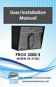
User/Installation Manual PROX 2000 II MODEL 23-213(i) Your “PARTNER” in Access Control www.americanaccess.
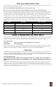
AAS 2Year Limited Warranty What item(s) this warranty applies to: American Access Systems “PROX 2000 II (23-XXXX series)” access controls. What is covered: Any defect in materials or workmanship. For how long: Two years from date of purchase. What we will do: If your AAS product is defective and returned within 2 years of the date of purchase, we will repair it or, at our option, replace it at no charge to you. If we repair your AAS product, we may use new or reconditioned parts.
PARTS CHECKLIST Enclosed with this box you should have the following items. Qty Description 1 Post Mount Station 1 16.5 VAC 20VA Transformer If any of the above items are missing from this box, contact American Access Systems Tools Needed For Basic Installation •• •• •• Wire strippers Wire cutters Digital or Analog multi-meter Technical/Customer Support 1-303-799-9757 or techsupport@securitybrandsinc.com Page 3 American Access Systems / Security Brands, Inc.
BEFORE PROCEEDING To take full advantage of the 24 month limited warranty, you must be registered with American Access SystemsS. Please read the enclosed warranty statement, (pg 2), fill out the warranty registration card provided and send it to: SECURITY BRANDS INC 1675 West Yale Ave. Englewood, CO 80110 phone: 303-799-9757 fax: 303-799-9756 sales@securitybrandsinc.com www.securitybrandsinc.
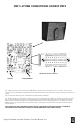
STEP 2-SYSTEM CONNECTIONS HOOKUP STEPS COMMUNICATIONS & RELAYS PRINTER POWER HOOKUP (A). Make all your prox slave connections BEFORE you apply power to the master unit. To connect power to your new post mount unit plug the tranformer into an outlet and connect the other end to the power plug on main circuit board. (B). Connect the device(s) to be controlled to the appropriate terminal(s). (C). Double check your connections. When you are sure you have the unit hooked up correctly, apply power to the unit.
USING A SLAVE WITH THE PROX 2000 II The prox 23-213 communicates with one additional slave proximity reader utilizing wiegand technology. . Please see instruction manual included with the 23-013. Note: Connect additional Proximity Reader to Slave 2 Communications only. Note: Do not run your gate control wires in the same shielded cable as your slave communication wires. There are two holes on the back of the unit which are for slave communication wires and gate control wires.
FUNCTION CODES FUNCTION CODE DESCRIPTION “Master Code” This is a 4 digit programmable code between 0000 and 9999 used for gaining access to the program mode. The factory default is “ 1 2 5 1”. “Relay A Latch Card” This is a user programmable card(s) used to lock down (or unlock) relay A. This code will be used to hold open a gate or door connected to relay A. “Relay B Latch Card” This is a user programmable card(s) used to lock down (or unlock) relay B.
MASTER RESET Follow these steps precisely. If you make an entry error, the unit will ERROR and you will have to start over. (1). Disconnect power from the master board (2). Reconnect power to the board while holding down the RESET BUTTON (3). Release the reset button and enter * * * from the keypad. The unit will issue a GOODBEEP and the master code will be set back to 1 2 5 1. If the unit was locked in the sleep, lockA, or lockB mode, the unit will be released and returned to the idle state.
PROGRAMMING A person desiring access to the program mode will enter the present MASTER CODE. If the master code is valid the yellow LED will come on and the individual will be prompted with a QUICKBEEP to enter a 3 digit number corresponding to a SUBMODE. There are 4 groups of SUBMODES. Group 100 is for PROGRAMMING CODES, group 200 is for DELETING CODES, group 300 is MISCELLANEOUS SETTINGS and GROUP 400 is PRINT FUNCTIONS. There are a total of 26 different submodes to choose from.
GROUP 100 (PROGRAMMING CODES) “100” SUBMODE 100 (PROGRAM ACCESS CARDS) (BLOCK FORMAT) HELPFUL HINT: PAGE 18 IN THIS MANUAL IS AN ACCESS CARD LOG SHEET WHICH MAY BE PHOTO-COPIED FOR KEEPING TRACK OF ALL CARDS IN THE SYSTEM. DESCRIPTION: Access cards are cards given out to end users to gain access onto the property. The number of access cards you may program into the unit is reflected in the corresponding model number of the unit.
“102” SUBMODE 102 (PROGRAM SLEEP CARD(S)) (BLOCK FORMAT) DESCRIPTION: The SLEEP MODE is the mode of operation in which the unit shuts down and goes to sleep. Only MANAGERS CARDS are accepted into the system in this mode. The SLEEP CARD is accepted into the system from either of the 2 slaves. Each time the SLEEP CARD is entered, the sleep card #, date, and time are logged into the history buffer and the unit toggles in and out of the SLEEP MODE.
“106” SUBMODE 106 (SET SYSTEM FACILITY CODE(S)) DESCRIPTION: The facility code must be set, for any of your cards to work with the system. The facility code can usually be found on the back of your cards. The PROX 2000 can handle a maximum of 3 facility codes. Note: The facility codes for the unit must reside between 0 and 255.
GROUP 200 (DELETING CARDS) “200” SubMode 200 (DELETE CARDS) (BLOCK FORMAT) To delete a card(s) from memory, enter the 4 digit “MASTER CODE” followed by submode “200” followed by the “BEGINNING CARD NUMBER” and the “ENDING CARD NUMBER” to be deleted. (MASTER CODE) + 200 + (BEGINNING CARD NUMBER) + (ENDING CARD NUMBER ) EXAMPLE: TO DELETE CARDS 120 THRU 155 1251 + 200 + 0120 +0155 EXAMPLE: TO DELETE A SINGLE CARD, SAY CARD NUMBER 38.
“302” SubMode 302 (SET CLOCK TIME) To set the clock time enter the 4 digit “MASTER CODE” followed by submode “302” then the “HOURS” and “MINUTES” of the day in military format. (MASTER CODE) + 302 + (HOURS) + (MINUTES) Example: 8:23 a.m. = “08” + “23” 5:00 p.m. = “17” + “00” The unit will respond with a GOODBEEP and exit from the program mode after the TIME has been accepted into the unit. Should you make an entry error, simply press the * key and reenter the correct data.
An easy way to check if the APB feature is enabled or not is to press (MASTER CODE) +308 and check if the red LED is on or off. If it’s on, the submode is enabled. Then press the # key to exit. To disable Anti-passback press: (MASTER CODE) + 308 + (MASTER CODE) APB MASTER CODE DESCRIPTION: The APB master code is used to erase the APB status of a certain code in the system.
“403” SubMode 403 (SET PRINTER BAUD RATE) The default baud rate is 9600. To program in a different baud rate choose from these 4 choices and put in the number 1 thru 4. (MASTER CODE) + 403 + (1,2,3 OR 4) Example: To change to 2400 baud: “MASTER CODE” + 403 + 3 “404” SubMode 404 (RED PRINTING ON INVALID CODES) This option is only available if you are using an AAS idp562 citizen printer. The option will print out every invalid code in red. This feature is disabled by default.
Access Name Page 17 American Access Systems / Security Brands, Inc.
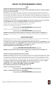
MASTER BOARD RESET BUTTON CONNECTION FOR 12 VOLT BULB CONNECTOR FOR COMMUNICATIONS AND RELAYS BOARD PRINTER POWER TRANSFORMER PLUG-IN SEE PAGE 6 WIEGAND COLOR CODES FOR SLAVE INTERFACE COMMUNICATIONS AND RELAYS BOARD Page 18 American Access Systems / Security Brands, Inc.
Customer Service and Tech Support Customer Service: 303-799-9757 Customer service is available free of charge. Hours are 8:00 a.m. to 4:30 p.m. MST. If you call, please have your Model and Serial Number to help our Technicians assist you. E-Mail: customerservice@securitybrandsinc.com Technical Support: 303-799-9757 Technical support is available free of charge. Hours are 8:00 a.m. to 4:30 p.m. MST. If you call, please have your Model and Serial Number to help our Technicians assist you.
Your “partner” in access control www.securitybrandsinc.