AMERICAN ACCESS SYSTEMS ADVANTAGE DK INSTALLATION AND PROGRAMMING INSTRUCTIONS MODELS ADV-05(i) thru 1000(i) Revision D Please Read Before Using This Equipment TECHNICAL SUPPORT: 303-799-9757 Monday thru Friday 8:30 a.m. - 5:00 p.m.
Year Warranty What item(s) this warranty applies to: American Access Systems "ADVANTAGE DK" access controls. What is covered: Any defect in materials or workmanship. For how long: Two years from date of purchase. What we will do: If your AAS product is defective and returned within 2 years of the date of purchase, we will repair it or, at our option, replace it at no charge to you. If we repair your AAS product, we may use new or reconditioned parts.
PARTS CHECKLIST Enclosed with this box you should have the following items.
Page 3
BEFORE PROCEEDING To take full advantage of the 24 month limited warranty, you must register with American Access Systems, Inc. Please read the enclosed warranty statement, (pg. 1), fill out the warranty registration card provided, and send it to: American Access Systems, Inc. Warranty Registration 7079 South Jordan Road / Unit 6 Englewood, Co.
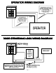
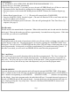
HARNESS COLOR CODES WHITE WHITE GREEN 11.5 - 29 volts AC or DC EARTH GROUND BROWN ORANGE BLUE RELAY A (PRIMARY) CONTROL COLOR CODES RELAY (A) COMMON RELAY (A) NORMALLY OPEN (N/O) RELAY (A) NORMALLY CLOSED (N/C) GRAY VIOLET YELLOW RELAY B (SECONDARY) CONTROL COLOR CODES (Used only if controlling a second device) RELAY (B) COMMON RELAY (B) NORMALLY OPEN (N/O) RELAY (B) NORMALLY CLOSED (N/C) Hookup Steps (A). Your unit operates between 11.5 volts minimum and 29 volts AC maximum.
ACCESS & FUNCTION CODES Depending on which model you have, your unit may be programmed with multiple (4 digit) access codes, the number of access codes is reflected in the model number (eg. ADV-15(i) = 15 access codes). There are two different types of codes, access codes & function codes. Although the number of access codes will vary with each model, the number of function codes is always 3.
UNIT RESET (!!!!! WARNING: ALL CODES WILL BE DELETED FROM MEMORY !!!!!) * (Please See pg. 6 for further information) Follow these steps precisely. If you make an error, the unit will ERROR and you will have to start over. ⇒ Disconnect power from the unit by pulling the wire harness away from the board. ⇒ Reconnect power to the board while holding down the RESET button (See location diagram, pg. 11 ).
SUB-MODE DESCRIPTION 1 2 3 4 5 6 7 8 9 0 ♦ Program Access Codes (Relay A) Delete Codes Change Master Code Set Sleep Code Set Latch Code Set Relay Output Times Program Access Codes (Relay B) Enable / Disable "3 Strikes-You’re Out" Program Event Input Erase Memory Sub-Mode 1 (Program Relay A Access Codes) To program new Relay A access codes enter the following; (MASTER CODE) + 1 + (NEW CODE) + (NEXT NEW CODE) etc.........
♦ Sub-Mode 4 (Set Sleep Code) EXPLANATION: The sleep code is used to disable all Relay A and function codes from the keypad. This feature is most commonly used in applications where no entry is desired after hours. Relay B codes will still be valid from the keypad. By connecting both relays in parallel, managers may be assigned RelayB codes and still gain access. While in the SLEEP MODE, the yellow and red LED's will flash approximately once every 3 seconds.
♦ Sub-Mode 7 (Program Relay B Access Codes) To program new Relay B access codes enter the following; (MASTER CODE) + 7 + (NEW CODE) + (NEXT NEW CODE) etc......... ( # to exit) Should you make a code entry error, simply press the * key and enter the correct code. You may select any 4 digit code you wish. If you receive an ERROR after entry, you must select another code as it is already in use. The unit will respond with a GOOD BEEP with the acceptance of each new Relay B code.
◊ To program the event input as Remote Inactive enter the following; (MASTER CODE) + 9 (*current mode) + 1 ◊ To program the event input as an Arming Circuit enter the following; (MASTER CODE) + 9 (*current mode) + 2 ◊ To program the event input as Remote Open enter the following; (MASTER CODE) + 9 (*current mode) + 3 + (*Relay to Activate) ◊ To DISABLE the event input enter the following; (MASTER CODE) + 9 (*current mode) + 0 *Current Mode Single beep = Remote Inactive Mode Enabled.
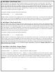
BOARD LAYOUT Yellow LED 5 Volt Lamp Connection pagePage 12 12 Event Input Red LED
Notes Page 13
Notes Page 14
American Access Systems Inc. 7079 South Jordan Road #6 Englewood, Co. 80112 Sales: 1-800 541-5677 E-mail: sales@americanaccess.com Customer Service: 1-303-799-9757 E-mail: customerservice@americanaccess.com Tech-Support: 1-303-799-9757 E-mail: techsupport@americanaccess.