THE TRACTOR AND/OR LOADER (IF EQUIPPED) Read the tractor and/or loader operator’s manual to learn how to operate your tractor and/or loader safely. Failure to do so could result in serious injury or death and equipment damage.
5
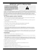
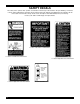
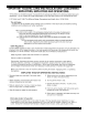
SAFETY DECALS The safety of the operator was a prime consideration in the design of the backhoe. Proper shielding, convenient controls, simple adjustments and other safety features have been built into this implement. The following decals are located on the backhoe. Keep decals clean and replace them immediately if they are missing. Contact your dealer or Amerequip for replacements.
7
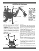
Dipper-Stick Safety Swing Lock Position Bucket Boom Mainframe Figure 1 Stabilizer Cylinder Boom Safety Lock Position Stabilizer The speed at which the backhoe operates is partially dependent on engine RPM. Use a moderate engine speed to start and increase it as your experience permits. Refer to “DIMENSIONS AND SPECIFICATIONS” on Page 44 for hydraulic flow volume requirements. When powering from tractor systems with higher output, reduce engine RPM to obtain acceptable backhoe operating speed.
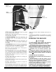
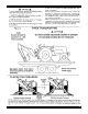
Figure 3 Safety Locks Swing Safety Lock POSITION ONLY Boom Safety Lock OPERATING THE BACKHOE 3. LOWER the stabilizers until the rear of the tractor is totally supported by them. NOTE: Rear tires should not come up off of the ground.
TRANSPORTING THE BACKHOE: 10
4. USE accessory lights and SMV emblem when traveling on highways. Before leaving backhoe operator’s seat, position the backhoe for transport by raising boom, crowding dipperstick in, swinging to center and raising the stabilizers. ALWAYS engage safety locks as shown in Figs. 1 and 3 when transporting. When transporting for long distances, periodically examine the backhoe and raise stabilizers and bucket back up to the full transport height.
12
Dig with the backhoe uphill whenever possible.
SERVICE HYDRAULIC SYSTEM On PTO pump contained systems, maintain the reservoir oil at the proper level by looking at the dipstick. The dipstick/breather cap is located directly behind the right hand foot pad on the backhoe. When checking oil level, the backhoe should be extended to full reach with the bucket rolled back and resting on the ground. All cylinders are retracted except for the boom cylinder.
Lower stabilizers to the ground, extend dipperstick and bucket and lower boom so bucket rests on the ground as shown in Figure 6. Refer to these illustrations for the location of all grease fittings. Periodically, check to be sure all bolts and nuts are tight. See torque chart, page 27. LUBRICATION *IMPORTANT: Before greasing boom to swing frame pivot (*) shown in Figure 6, raise boom and install boom safety lock pin shown in Figure 1. The following locations should be oiled with SAE30 oil: A.
Figure 7 REMOVAL FROM TRACTOR - STORAGE Backhoe Shown Partially Extended Backhoe Fully Extended Blocking For Support 3. Raise the backhoe operator’s seat until it’s in the raised position.
The backhoe is supplied with flip-over stabilizer pads as standard equipment. They are suitable for most backhoe work and generally are all that is ever required. However, street pad kits are available as options. This kit bolts to the standard pads and increase the versatility of the backhoe. See Figure 8.
24. Relief valve setting in backhoe control valve too low or defective - relief pressure will have to be checked and corrections made. Backhoe system pressure is 2400 psi. Relief valve may need cleaning and overhauling, or entire cartridge must be replaced. See item 30 at the end. 25. Overload relief valve in the control valve stuck open or malfunctioning - clean relief carefully but do not disturb its pressure setting as it cannot be field calibrated, or replace cartridge. See item 30 at the end. 26.
Figure 9 19
Figure 10. - Figure 10 C Figure 10 B A G 20 I F H D Reposition stabilizer cylinders from their shipping configuration (See Fig. 11), by assembling them into the Mainframe, using pins and hardware provided. Be sure cylinder ports are pointed upward and hoses are routed above the cylinder to mainframe pivot pin connection. See Fig. 12. 2. Support boom(A) and dipperstick(B) with hoist and remove boom transport lock pin. Lower boom and manually extend dipperstick until it rests on ground.
3. Remove plastic bag containing bucket pins from backhoe. Attach bucket (D) to dipperstick using one pin, two bolts, nuts, lockwashers, pin retainers and washers as needed to take up gap under pin retainers. 4. Attach bucket link (E) to bucket, using same hardware as listed for step #3. 5. Reposition hoist to backhoe to prevent tipping.
22 Figure 13 10 11 12
ATTACHING KIT INSTRUCTIONS 3-POINT HITCH LINKAGE & HYDRAULIC HOOK-UP TO TRACTOR HYDRAULIC SYSTEMS Mounting and hydraulic kits may include two hoses which can be used in connecting the backhoe control valve to the tractor hydraulic system. Additional hydraulic components or kits will be required to complete the hook-up to the tractor hydraulic system. Refer to “Hydraulic Hook-up” section for further information. Pump and reservoir kits are available as options. Figure 13.
Figure 14 HYDRAULIC HOOK-UP 24
2.
Figure 17 The hook-up of the Backhoe to the closed-center system requires more than connecting it to the remote couplers.
27
PTO PUMP AND RESERVOIR KIT General Description The PTO Pump Kit consists of those parts required to power the backhoe from the tractor’s PTO shaft. It includes the PTO pump and adapter, reservoir, filtration system, hydraulic hoses and fittings. In addition, it includes a pump torque arm which attaches to the tractor’s lower link and keeps the pump from turning with the PTO shaft. Note: The speed of the backhoe operation increases as PTO speed increases.
PTO PUMP KIT PARTS BREAKDOWN W702 8 1/2' BACKHOE Figure 19 12 W702 8 1/2 Foot Backhoe PTO Pump And Reservoir Kit 12 28 17 Index Number 1 2 3 4 5 6 7 8 9 11 12 13 14 15 16 17 18 19 Part Number 860296 23067 15526 11026 7975 780833 14150 10375 7987 7974 17538 6740 8061 8146 10376 17519 858135 23072 Description Filler Tube Breather Cap with Dipstick Reservoir Tank Suction Hose Street Elbow, 3/4 NPTM x 3/4 NPTF x 90° Hose Nipple Hose Clamp - 1-1/16” to 2” Filter Base and Element Reducer - 3/4 NPTM
3-POINT MOUNT KIT PARTS BREAKDOWN W701 FOR 8 1/2' BACKHOE 10 11 12 Index Number 1 2 3 4 5 6 7 8 9 10 11 12 13 18 19 20 21 22 30 Part Number 861755 861760 861735 7092 8173 7515 50824 50825 6577 8152 8071 7431 6798 775003 8582 8624 852198 860292 Description RH Lower Link Weldment LH Lower Link Weldment Adapter Weldment Bolt, 1/2 NF x 7-1/2" GR.
W604 STREET PAD KIT Index No.
REGULAR DUTY DEEP PROFILE BUCKET Index Number 1 2 3 Part Number W710 13613 13617 Description Regular Duty Deep Profile Bucket - 12" Tooth and Shank Assemblies for 12" Bucket Tooth Point Only for 12" Bucket 1 2 3 W712 13613 13617 Regular Duty Deep Profile Bucket - 24" Tooth and Shank Assemblies for 24" Bucket Tooth Point Only for 24" Bucket W714 13613 13617 Regular Duty Deep Profile Bucket - 40" Tooth and Shank Assemblies for 40" Bucket Tooth Point Only for 40" Bucket 1 2 3 1 2 3 1 2 3 W711 13613 1
33
34
35
CONTROL TOWER AREA 36
STABILIZER LEG AREA 37
SWING SYSTEM AREA 38
BOOM, DIPPERSTICK, AND BUCKET AREA 39
HYDRAULIC PLUMBING 76 58 59 59 58 59 58 57 54 54 86 87 52 75 78 84 52 75 85 57 78 140 74 75 84 29 55 99 TO BOOM WELDMENT 52 52 40 51 74 139 52 60
HYDRAULIC PLUMBING 58 58 58 58 83 83 53 82 82 52 52 52 G IN W S 82 56 82 56 G IN W S 52 52 52 74 52 52 74 41
Buffer Seal *Not available as a separate repair part - order Seal Repair Kit. IMPORTANT - Replace cylinder nut (1) any time nut must be removed, and torque to proper value shown. Cylinder Data: CYLINDER *184 - BOOM *184 - DIPPER 183 - BUCKET PISTON DIA. 21⁄2" 21⁄2" 21⁄4" STROKE 21" 21" 18" 182 - STABILIZER 21⁄2" 15 13/16" 1 2 ⁄4" 10" 186 - SWING *Identical cylinders used for both functions. 42 RETRACTED EXTENDED PIVOT PIN TYPE OF LENGTH LENGTH ROD DIA. DIA.
HYDRAULIC CYLINDERS FOR MODEL 8600 43
BACKHOES - DIMENSIONS AND SPECIFICATIONS 9'0" 8'6" 2550 PSI 44
MAIN SYSTEM RELIEF VALVE (2400 PSI) Location: Left Hand Valve Cover 45
CONTROL VALVE SECTION Typical Section for Actuate (Bucket) & Swing Circuits 46
CONTROL VALVE SECTION Typical Section for Actuate (Bucket) & Swing Circuits 47
CONTROL VALVE SECTION Typical Section for Crowd Circuit 48
CONTROL VALVE SECTION Typical Section for Crowd Circuit 49
CONTROL VALVE SECTION Typical Section for Lift Circuit 50
CONTROL VALVE SECTION Typical Section for Lift Circuit 51
CONTROL VALVE SECTION Typical Section for Actuate Stabilizer Circuits 52
CONTROL VALVE SECTION Typical Section for Actuate Stabilizer Circuits 53
SERVICE NOTES:
SERVICE NOTES: