
Installation guide

SS3GR1028F Series Installation Guide Chapter 2 Hardware Installation
socket (with overload and leakage protection), and the other end to the power socket in
the back panel of the switch.
2. Check the power status indicator in the front panel of the switch. The corresponding
power indicator should light. The SS3GR1028F series is self-adjustable for the input
voltage. As soon as the input voltage is in the range printed on the switch surface, the
switch can operate correctly.
3. When the switch is powered on, it executes self-test procedure and startups.
Caution!
The input voltage must be within the required range, otherwise the switch can be
damaged or malfunction. Do not open the switch shell without permission. It can cause
physical injury.
2.3.9 DC Power Supply Connection
The SS3GR1028F series supports 220V AC input, 48V DC input or 220V AC, 48V DC
input simultaneously. 48V DC input connection procedure is described as below:
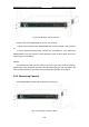
1. Insert DC power linker provided in the accessory kit into DC power source socket in the
back panel of the switch.
2. Check whether the power status indicator is light in the front panel of the switch.
3. When the switch is powered on, it executes self-test procedure and startups.
Caution!
The input voltage must be within the required range, otherwise the switch can be
damaged or malfunction. Do not open the switch shell without permission. It can cause
physical injury.
2.3.10 PoE Power Supply Connection
When using PoE function of The SS3GR1028F, it needs to connect the external PoE
power with 5 holes socket. The connection procedure is described as below:
1. Insert one end of PoE power cable provided in the accessory kit into the external PoE
power (with overload and leakage protection), and the other end to PoE power socket in
the back panel of the switch.
2. Connect PD device to the front port of SS3GR1028F.
3. Check whether PD device is powered and the port indicator status shows the power
2-10