
Installation guide
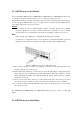

3. Repeat steps 1 and 2 for each unit in the stack. Form a simple chain starting at the Down port on the
top unit and ending at the Up port on the bottom unit (stacking up to 8 units).
4. (Optional) To form a wrap-around topology, plug one end of a stack cable into the Down port on the
bottom unit and the other end into the Up port on the top unit.
Stacking Topologies
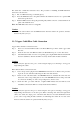
All units in the stack must be connected via stacking cable. You can connect units in a simple cascade
configuration, connecting Down ports to Up ports, from the top unit to the bottom unit. Using this
“line” topology, if any link or unit in the stack fails, the stack is split and two separate segments are
formed. The Stack Link LEDs on the units that are disconnected flash to indicate that the stack link
between them is not functioning (see Table 1-3 “System Status LEDs” on page 1-7).
When using line topology and a stack link failure occurs, the stack reboots and a Master unit is
selected within each of the two stack segments. The Master unit will be either the unit with the Master
button depressed or the unit with the lowest MAC address if the Master button is not depressed on any
unit. When the stack reboots and resumes operations, note that the IP address will be the same for both
of the stack segments. To resolve the conflicting IP addresses, you should manually replace the failed
link or unit as soon as possible. If you are using a wrap-around stack topology, a single point of failure
in the stack will not cause the stack to fail.
It would take two or more points of failure to break the stack apart. If the Master unit fails or is
powered off, the backup unit will take control of the stack without any loss of configuration settings.
The Slave unit with the lowest MAC address is selected as the backup unit.
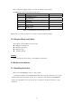
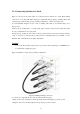
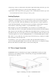
2.3.7 Power Supply Connection
SS3GR50i/26i switch uses 110v/220v AC power supply by default. Please read the power input
specification for the detailed information. -48V(12V) DC power supply and AC/DC redundancy
power input are also supported.
Figure 2-5 Attaching power cable to SS3GR50i/26i switch
2-10