
Installation guide
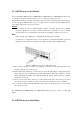


2.3.6 Connecting Switches in a Stack
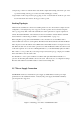
Figure 2-4 shows how the stack cables are connected between switches in a stack. Each stacking
connection is a 48 Gbps full-duplex high-speed serial link using proprietary stacking cables. The
switch supports a line and ring-topology stacking configuration, or can be used stand alone.
To ensure minimal disruption in case a unit or stacking cable fails, we recommend always use a
ring-topology.
In line-topology stacking there is a single stack cable connection between each switch that carries
two-way communications across the stack.
In ring-topology stacking, an extra cable is connected between the top and bottom switches forming a
“ring” or “closed-loop.” The closed-loop cable provides a redundant path for the stack link, so if one
link fails, stack communications can still be maintained.
Caution
To avoid the flood traffic caused by the loop connection, either spanning tree or MRPP needs to
be enabled and configured properly.
Figure 2-4 illustrates a ring-topology stacking configuration.
Figure 2-4 Making Stacking Connections
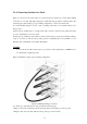
To connect up to eight switches in a stack, perform the following steps:
1. Plug one end of the stack cable (ordered separately) in the Down (right) port of the top unit.
2. Plug the other end of the stack cable into the Up (left) port of the next unit.
2-9