
Installation guide
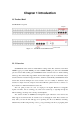
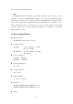
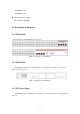
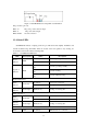

Figure 1-4 SS3GR50I DC Power Input Pin-outs Distribution
DC power has 3 pin-outs:
PIN1: V+ DC power positive electrode input
PIN2: V- DC power cathode input
PIN3: CGND Ground connection
1.3.4 Status LEDs
SS3GR50i/26i includes a display panel and port indications that simplify installation and
network troubleshooting. The LEDs, which are located on the front panel for easy viewing, are
shown below and described in the following table.
Table 1.1 SS3GR50i/26i LED Status
LED Panel Symbol Status Description
On (Green) Power is operating normally.
Power
Indicator
PWR
Off Power is off.
On (Green, blink at 1
Hz)
System is operating normally.
On (Green, blink at 8
Hz)
System is loading.
Operation
indicator
RUN
On (Red, blink at 8
Hz)
System is malfunctioning.
RJ-45 Port Indicator
On (Green) RJ-45 port is connected.
Status
Indicator
On the left
Off RJ-45 port is not connected.
Transfer
Indicator
On the right Blink (Green) Sending or receiving data
SFP Port Indicator
On (Green) SFP transceiver is connected.
Status
Indicator
On the left
Off SFP transceiver is not connected.
Transfer
Indicator
On the right Blink (Green) Sending or receiving data
XFP Port Indicator
Status Link
On (Green) XFP transceiver is connected.
1-5