SS3GR50i / SS3GR26i L3 Gigabit Ethernet Switch With IP Stacking Installation Guide (v1.
Copyright © Amer.com Corp., 1997-2007 All rights reserved. No part of this publication may be reproduced in any form or by any means or used to make any derivative such as translation, transformation, or adaptation without permission from Amer.com, as stipulated by the United States Copyright Act of 1976. Amer.com reserves the right to make changes to this document and the products which it describes without notice. Amer.
Overview SS3GR50i/26i switch is a high performance route switch, that can be deployed as aggregation equipment for IP metropolitan area networks (MAN). SS3GR50i/26i switch can seamlessly support various network interfaces from 10Mb, 100Mb, 1000Mb to 10Gb Ethernets. We strongly recommend you to read through this manual carefully before installing and configuring to avoid possible damage to the switch and malfunction.
FCC - Class A This equipment has been tested and found to comply with the limits for a Class A digital device, pursuant to part 15 of the FCC Rules. These limits are designed to provide reasonable protection against harmful interference when the equipment is operated in a commercial environment. This equipment generates, uses, and can radiate radio frequency energy and, if not installed and used in accordance with the instruction manual, may cause harmful interference to radio communications.
Table of Contents Overview....................................................................................................................... iii Table of Contents ............................................................................................................ v Chapter 1 Introduction .................................................................................................1-1 1.1 PRODUCT BRIEF ................................................................................1-1 1.1.
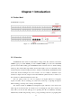
Chapter 1 Introduction 1.1 Product Brief SS3GR50i/26i front panel: Figure 1-1 SS3GR50i and SS3GR26i Switch 1.1.1 Overview SS3GR50i/26i switch switch are 10Gb Ethernet routing switch. The switch has 48/24 fixed 1000Mb copper ports (44/20 1000Mb ports and 4 1000Mb COMBO ports) and 2 fixed 10Gb XFP ports and 2 fixed 10Gb stacking ports.SS3GR50i/26i switch switch are based on 10Gb switching technology. The switches fully support IPv6, whereas their height is only 1U.
into separate broadcast domains with IEEE 802.1Q compliant VLANs, empowers multimedia applications with multicast switching and CoS services, and eliminates conventional router bottlenecks. These switches can be used to augment or completely replace slow legacy routers, off-loading local IP traffic to release valuable resources for non-IP routing or WAN access. With wire-speed performance for Layer 2 and Layer 3, these switches can significantly improve the throughput between IP segments or VLANs. 1.1.
port level security and block illegal users. QoS SS3GR50i/26i switch switch fully support DiffServ Module. Users can specify a queue bandwidth on each port. WRR/SP/SWRR scheduling is also supported. SS3GR50i/26i switch supports the port security. Users can deploy trusted CoS, DSCP, IP precedence and port priority. User can also modify packets’ DSCP and COS values. The traffic can be classified by port, VLAN, DSCP, IP precedence and ACL table. User can also modify packets’ DSCP and IP precedence values.
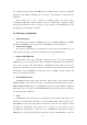
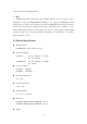
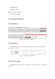
SS3GR50i: 6.1 kg SS3GR26i: 5.7 kg Mean Time Between Failure Min. 80, 000 Hours MTBF 1.3 Description of Hardware 1.3.1 Front Panel The front panel of SS3GR50i/26i is shown below: Figure 1-2 Front Panel of SS3GR50i/26i 1.3.2 Back Panel SS3GR50i/26i: There are 1x 110v/220v AC power receptacle, 1x12v DC power receptacle and 1x ground connection. Figure 1-3 Back Panel of SS3GR50i/26i 1.3.3 DC Power Input SS3GR50i/26i supports AC/DC power redundancy.
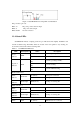
Figure 1-4 SS3GR50I DC Power Input Pin-outs Distribution DC power has 3 pin-outs: PIN1: V+ DC power positive electrode input PIN2: V- DC power cathode input PIN3: CGND Ground connection 1.3.4 Status LEDs SS3GR50i/26i includes a display panel and port indications that simplify installation and network troubleshooting. The LEDs, which are located on the front panel for easy viewing, are shown below and described in the following table. Table 1.
Indicator Transfer Indicator Table 1.2 Act Off XFP transceiver is not connected.
1.3.
Chapter 2 Hardware Installation 2.1 Installation Notice To ensure the proper operation of SS3GR50i/26i switch and your physical security, please read carefully the following installation guide. 2.1.1 Environmental Requirements The switch must be installed in a clean area. Otherwise, the switch may be damaged by electrostatic adherence. Maintain the temperature within 0 to 50 °C and the humidity within 5% to 95%, non-condensing. The switch must be put in a dry and cool place.
Gas Average (mg/m³) Max (mg/m³) SO2 0.2 1.5 H2S 0.006 0.03 NO2 0.04 0.15 NH3 0.05 0.15 Cl2 0.01 0.3 Table 2.2 Environmental Requirements: Particles 2.1.1.2 Temperature and Humidity Although the switch is designed to use 4 fans, the site should still maintain a desirable temperature and humidity. High-humidity conditions can cause electrical resistance degradation or even electric leakage, degradation of mechanical properties and corrosion of internal components.
of the power supply system. The input source for the switch should be reliable and secure, a voltage adaptor can be used if necessary. The building’s circuit protection system should include in the circuit a fuse or circuit-breaker of no greater than 240 V, 10 A. It is recommended to use a UPS for more reliable power supplying. . Caution Improper power supply system grounding, extreme fluctuation of the input source, and transients (or spikes) can result in larger error rate, or even hardware damage! 2.1.
When mounting devices in an open rack, care should be taken to prevent the rack frame from obstructing the switch ventilation openings. Be sure to check the positioning of the switch after installation to avoid the aforementioned. Caution If a standard 19’’ rack is not available, the SS3GR50i/26i can be placed on a clean level desktop, leave a clearance of 10mm around the switch for ventilation, and do not place anything on top of the switch. 2.1.
Please unpack the shipping package and verify carefully the contents inside. SS3GR50i/26i switch should include the followings: ITEM No. Part name Number 1 SS3GR50i/26i switch 1 2 AC power cable 1 3 Manual CD 1 4 Console cable 1 5 Chassis bracket 2 6 Bracket screw 4 Figure 2.4 SS3GR50i/26i switch Packaging Contents Note: The above contents are subject to the received contents within the package. 2.2.
Figure 2-1 Rack-mounting SS3GR50I Caution The brackets are used to fix the switch on the rack. They can’t serve as a bearing. Please place a rack shelf under the switch. Do not place anything on top of the switch. Do not block the blowholes on the switch to ensure the proper operation of the switch. 2.3.2 Connecting Console SS3GR50i/26i switch has a RJ45 console port, which can be connected with a RJ45 to DB9 serial cable (also comes with the device).
2.3.3 SFP Transceiver Installation An optional Gigabit SFP transceiver (1000BASE-SX, 1000BASE-LX or 1000BASE-LH) can be used for a backbone connection between switches, or for connecting to a high-speed server. Each single-mode fiber port requires 9/125 micron single-mode fiber optic cable with an LC connector at both ends. Each multimode fiber optic port requires 50/125 or 62.5/125 micron multimode fiber optic cabling with an LC connector at both ends.
The switch has 2 10Gb fiber transceiver slots. The procedure for installing the XFP 10Gb fiber transceiver is shown below: Step 1: Put on an ESD wrist strap (or antistatic gloves) Step 2: Insert the XFP transceiver to the guide rail inside the 10Gb line card. Do not to put the XFP transceiver up-side-down. Step 3: Push the XFP transceiver along the guide rail gently until it comes into contact with the front panel of the 10Gb line card. Note: The XFP 10Gb transceiver is hot swappable.
2.3.6 Connecting Switches in a Stack Figure 2-4 shows how the stack cables are connected between switches in a stack. Each stacking connection is a 48 Gbps full-duplex high-speed serial link using proprietary stacking cables. The switch supports a line and ring-topology stacking configuration, or can be used stand alone. To ensure minimal disruption in case a unit or stacking cable fails, we recommend always use a ring-topology.
3. Repeat steps 1 and 2 for each unit in the stack. Form a simple chain starting at the Down port on the top unit and ending at the Up port on the bottom unit (stacking up to 8 units). 4. (Optional) To form a wrap-around topology, plug one end of a stack cable into the Down port on the bottom unit and the other end into the Up port on the top unit. Stacking Topologies All units in the stack must be connected via stacking cable.
1. Insert one end of the power cable provided in the accessory kit into the power source socket (with overload and leakage protection), and the other end to the power socket in the back panel of the switch. 2. Check the power status indicator in the front panel of the switch. The corresponding power indicator should light. SS3GR50i/26i switch is self-adjustable for the input voltage. As soon as the input voltage is in the range printed on the switch surface, the switch can operate correctly. 3.