FCC Compliance Statement: This equipment has been tested and found to comply with limits for a Class B digital device, pursuant to Part 15 of the FCC rules. These limits are designed to provide reasonable protection against harmful interference in residential installations. This equipment generates, uses, and can radiate radio frequency energy, and if not installed and used in accordance with the instructions, may cause harmful interference to radio communications.
Declaration of Conformity We, Manufacturer/Importer (full address) G.B.T.
7ZXR TM AMD Athlon AGP Motherboard USER'S MANUAL AMDTM Athlon Socket A Processor Motherboard REV. 1.
How This Manual Is Organized This manual is divided into the following sections: 1) Revision History Manual revision information 2) Item Checklist Product item list 3) Features Product information & specification 4) Hardware Setup Instructions on setting up the motherboard 5) Performance & Block Diagram Product performance & block diagram 6) Suspend to RAM & Dual BIOS Instructions on STR installation & Dual BIOS 7) Four Speaker & SPDIF Four Speaker & SPDIF introduction 8) @BIOS & Easy Tune///T
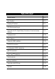
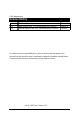
Table Of Content Revision History P.1 Item Checklist P.2 Summary of Features P.3 7ZXR Motherboard Layout P.5 Page Index for CPU Speed Setup / Connectors / Panel and Jumper Definition P.6 Performance List P.23 Block Diagram P.24 Suspend to RAM Installation P.25 Dual BIOS Introduction P.31 Four Speaker & SPDIF Introduction P.38 @BIOS Introduction P.43 Easy Tune///TM Introduction P.44 Raid Introduction P.46 Memory Installation P.69 Page Index for BIOS Setup P.70 Appendix P.
7ZXR Motherboard Revision History Revision 1.0 1.0 Revision Note Initial release of the 7ZXR motherboard user’s manual. Second release of the 7ZXR motherboard user’s manual. Date Sep.2000 Oct.2000 The author assumes no responsibility for any errors or omissions that may appear in this document nor does the author make a commitment to update the information contained herein. Third-party brands and names are the property of their respective owners. Oct. 05, 2000 Taipei, Taiwan, R.O.
Item Checklist Item Checklist ;The 7ZXR motherboard ;Cable for IDE / floppy device ;Diskettes or CD (TUCD) for motherboard driver & utility ;7ZXR user’s manual 2
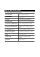
7ZXR Motherboard Summary Of Features Form CPU Factor Chipset 30.5 cm x 24.4 cm ATX size form factor, 4 layers PCB.
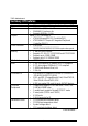
Summary of Features PS/2 Connector On-Board Sound On-Board Raid BIOS Additional Features PS/2 Keyboard interface and PS/2 Mouse interface y Creative CT5880 sound y AC’97 CODEC y Line In/Line Out/Mic In/AUX In/CD In/TEL/Game Port /Four Speaker & SPDIF y Support data striping (RAID 0) or mirroring (RAID 1) . y Supports concurrent dual IDE controller operation. y Supports IDE bus master operation. y Displays status and error checking messages during boot-up.
7ZXR Motherboard 7ZXR Motherboard Layout PS/2 JP4 ATX POWER USB1 J3 COM A Socket A CPU LPT JP6 COM B JP8 LED1 J15 JP7 Clock Generator PCI1 IDE4 JP19 Sigmtal PCI2 VT82C 686A JP20 BAT1 PCI3 JP3 J16 J2 JP10 PCI4 Creative J13 PCI5 JP16 AMR J12 JP17 MAIN BACK Up BIOS BIOS BZ1 ISA 1 5 USB2 J4 J11 JP11 CT5880 JP9 JP18 FLOPPY IDE1 AGP 1 IDE3 SW1 IDE2 7ZXR DIMM3 DIMM1 DIMM2 J18 GAME & AUDIO VT8363
7ZXR Motherboard Layout Page Index for CPU Speed Setup/Connectors/Panel and Jumper Definition CPU Speed Setup Connectors ATX Power COM A / COM B / LPT Port Floppy Port Game & Audio Port IDE 1/IDE2 (Primary/Secondary), IDE3/IDE4(Promise Raid/ATA100) Port J2 (System Fan) J3 (CPU Fan) J4 (IR) J12 (Wake On LAN) J13 (Ring Power On) J15 (AUX_IN) J16 (TEL) J18 (CD Audio Line In) JP6 (Power Fan) JP8 / LED1 (STR LED Connector & DIMM LED) PS/2 Keyboard & PS/2 Mouse Connector USB 1 Connector USB 2 Connector Panel a
7ZXR Motherboard CPU Speed Setup The system bus speed is selectable at 100~133MHz. The user can select the system bus speed by DIP switch SW1. Set System Bus Speed zIf your clock generator (in Motherboard) is ICW W230H. You can follow the below reference. SW1: (ICW W230H) FSB 95 Ë100 102 104 106 108 110 112 133 1 O 0 0 X 0 0 0 0 0 O : ON, X : OFF 2 O X 0 X X 0 X 0 X 3 X X 0 X X X 0 0 0 4 X X X 0 0 0 0 0 X W230H Ë The FSB Speed of the VIA KT133 is 100MHz.
Connectors Connectors ATX Power 10 20 1 11 Pin No. Definition 3,5,7,13, GND 15-17 1,2,11 3.
7ZXR Motherboard Floppy Port Red Line FDD1 Game & Audio Port Game Port Line Out 1 MIC In Line In Line Out 1: Line Out or SPDIF (The SPDIF output is capable of providing digital audio to external speakers or compressed AC3 data to an external Dolby digital decoder). To enable SPDIF, simply insert SPDIF connector into Line Out1. Line Out1 will become SPDIF Out automatically. (see page 35 for more information).
Connectors IDE1,IDE2 (Primary/Secondary),IDE3/IDE4(Raid/ATA100) Port Red Line IDE 1 IDE 2 IDE 3 IDE 4 J2 : System Fan 1 Pin No.
7ZXR Motherboard J3 : CPU Fan 1 Pin No. Definition 1 Control 2 +12V 3 SENSE J4 : IR 1 Pin No.
Connectors J12 : Wake On LAN 1 Pin No. Definition 1 +5V SB 2 GND 3 Signal J13 : Ring Power On (Internal Modem Card Wake Up) 1 Pin No.
7ZXR Motherboard J15 : AUX_IN 1 Pin No. 1 2 3 4 Definition AUX-L GND GND AUX-R J16 TEL : The connector is for Modem with internal voice connector 1 Pin No.
Connectors J18 : CD Audio Line In 1 Pin No. 1 2 3 4 Definition CD-L GND GND CD-R JP6 : Power Fan 1 Pin No.
7ZXR Motherboard JP8 / LED1: STR LED Connector & DIMM LED STR LED Connector External. 1 + DIMM LED PS/2 Keyboard & PS/2 Mouse Connector PS/2 Mouse/Keyboard Pin No.
Connectors USB 1 Connector 1 2 34 5 67 8 Pin No. 1 2 3 4 5 6 7 8 Definition USB V0 USB D0USB D0+ GND USB V1 USB D1USB D1+ GND USB 2 Connector 2 10 1 9 16 Pin No.
7ZXR Motherboard Panel And Jumper Definition BAT1: Battery + )Danger of explosion if battery is incorrectly replaced. )Replace only with the same or equivalent type recommended by the manufacturer. )Dispose of used batteries according to the manufacturer’s instructions.
Panel and Jumper Definition GN (Green Switch) GD (Green LED) HD (IDE Hard Disk Active LED) SPK (Speaker Connector) RE (Reset Switch) P+P−P−(Power LED) PW (Soft Power Connector) Open: Normal Operation Close: Entering Green Mode Pin 1: LED anode(+) Pin 2: LED cathode(−) Pin 1: LED anode(+) Pin 2: LED cathode(−) Pin 1: VCC(+) Pin 2- Pin 3: NC Pin 4: Data(−) Open: Normal Operation Close: Reset Hardware System Pin 1: LED anode(+) Pin 2: LED cathode(−) Pin 3: LED cathode(−) Open: Normal Operation Close: Power O
7ZXR Motherboard JP4: Rear USB Device Wake up Selection (USB Connector Æ USB1) 1 Pin No. Definition 1-2 Close Normal (Default) 2-3 Close USB Device Wake up USB1 (If you want to use "USB Dev Wakeup From S3-S5" function, you have to set the BIOS setting "USB Dev Wakeup From S3-S5" enabled, and the jumper "JP4" enabled). *(Power on the computer and as soon as memory counting starts, press . You will enter BIOS Setup.
Panel and Jumper Definition JP9 : Onboard Sound Function Selection JP9 1 Pin No. Definition 1-2 close Onboard Sound Enable (Default) 2-3 close Onboard Sound Disable JP10 : BIOS Write Protection (Optional) 1 Pin No.
7ZXR Motherboard JP11 : Front USB Device Wake up Selection (USB Port Æ USB2) USB2 1 Pin No. Definition 1-2 close Normal (Default) Enabled Front USB Device 2-3 close Wake up (If you want to use "USB Dev Wakeup From S3-S5" function, you have to set the BIOS setting "USB Dev Wakeup From S3-S5" enabled, and the jumper "JP11" enabled). *(Power on the computer and as soon as memory counting starts, press . You will enter BIOS Setup.
Panel and Jumper Definition JP19 : Onboard Promise Selection (Optional) 1 Pin No. 1-2 close Definition IDE Raid disabled (Promise chipset disabled) 2-3 close IDE Raid enabled(Default) (Promise chipset enabled) JP20 : Raid/ATA100 Selection (Optional) 1 Pin No. Definition 1-2 close Raid Function 2-3 close ATA 100 Function (Default) (If you want to use "Raid Function”, your IDE3 or IDE4 must be connected with Hard Driver.
7ZXR Motherboard Performance List The following performance data list is the testing results of some popular benchmark testing programs. These data are just referred by users, and there is no responsibility for different testing data values gotten by users. (The different Hardware & Software configuration will result in different benchmark testing results.
Block Diagram Block Diagram CPUCLK (100MHz) TM AMD-K7 AGP 2X/4X System Bus 100MHz AGPCLK (66MHz) VT8363 3.3V SDRAM 100/133MHz HCLK (100MHz) AGPCLK (66MHz) 33MHz PCI Bus 33MHz 14.318MHz 48MHz CT5880 Promise VT82C 686A PDC20265 Option AC-Link 66MHz AC97 CODEC 5 PCI Raid /ATA 100 IDE Port Channels AMR COM Ports LPT PS/2 Floppy Port Game Port ATA66 IDE Channels 4 USB Ports AMR PCI (33MHz) ISA AGPCLK (66MHz) HCLK (100MHz) PCI (33MHz) ICW W230H 48MHz 14.
7ZXR Motherboard Suspend To RAM Installation A.1 Introduce STR function: Suspend-to-RAM (STR) is a Windows 98 ACPI sleep mode function. When recovering from STR (S3) sleep mode, the system is able, to retrieve the last “state” of the system before it went to sleep and recover to that state in just a few seconds. The “state” is stored in memory (RAM) before the system goes to sleep.
Suspend to RAM Installation Step 2: (If you want to use STR Function, please set jumper JP7 Closed.) 1 Pin No. Open Close Definition Normal (Default) STR Enabled Step 3: Power on the computer and as soon as memory counting starts, press . You will enter BIOS Setup. Select the item “POWER MANAGEMENT SETUP”, then select “ACPI Sleep Type : S3 / STR”. Remember to save the settings by pressing "ESC" and choose the “SAVE & EXIT SETUP” option.
7ZXR Motherboard A.3 How to put your system into STR mode? 1. There are two ways to accomplish this: Choose the “Stand by” item in the “Shut Down Windows” area. A. Press the “Start” button and then select “Shut Down” B.
Suspend to RAM Installation 2. Define the system ”power on” button to initiate STR sleep mode: A. Double click “My Computer” and then “Control Panel” B. Double click the “ Power Management” item.
7ZXR Motherboard C. Select the “Advanced” tab and “Standby” mode in Power Buttons. Step 4: Restart your computer to complete setup. Now when you want to enter STR sleep mode, just momentarily press the “Power on” button. A.4 How to recover from the STR sleep mode? There are five ways to “wake up” the system: 1. 2. 3. 4. 5. Press the “Power On” button. Use the “Resume by Alarm” function. Use the “Modem Ring On” function. Use the “Wake On LAN” function. Use the “USB Device Wake Up” function.
Suspend to RAM Installation A.5 Notices : 1. 2. In order for STR to function properly, several hardware and software requirements must be satisfied: A. Your ATX power supply must comply with the ATX 2.01 specification (provide more than 720 mA 5V Stand-By current). B. Your SDRAM must be PC-100 compliant. Jumper JP8 is provided to connect to the STR LED in your system chassis. [Some chassis may not provide this feature.] The STR LED will be illuminated when your system is in STR sleep mode.
7ZXR Motherboard Dual BIOS Introduction A. What is Dual BIOS Technology? Dual BIOS means that there are two system BIOS (ROM) on the motherboard, one is the Main BIOS and the other is Backup BIOS. Under the normal circumstances, the system works on the Main BIOS. If the Main BIOS is corrupted or damaged, the Backup BIOS can take over while the system is powered on. This means that your PC will still be able to run stably as if nothing has happened in your BIOS. B. How to use Dual BIOS? a.
Dual BIOS Introduction b. AMI Dual BIOS Flash ROM Programming Utility AMI Dual BIOS Flash ROM Programming Utility Boot From……………………….. Main BIOS Main ROM Type………………… SST 39SF020 Backup ROM Type……………… SST 39SF020 Wide Range Protection Disable Boot From Main BIOS Auto Recovery Enable Halt On Error Disable Copy Main ROM Data to Backup Load Default Settings Save Settings to CMOS PgDn/PgUp:Modify ↑↓:Move ESC:Reset F10:Power Off c.
7ZXR Motherboard Boot From : Main BIOS (Default), Backup BIOS Status 1: The user can set to boot from main BIOS or Backup BIOS. Auto Recovery : Enabled(Default), Disabled When one of the Main BIOS or Backup BIOS occurs checksum failure, the working BIOS will automatically recover the BIOS of checksum failure. (In the Power Management Setup of the BIOS Setting, if ACPI Suspend Type is set to Suspend to RAM, the Auto Recovery will be set to Enable automatically.
Dual BIOS Introduction DualBIOSTM Technology FAQ GIGABYTE Technology is pleased to introduce DualBIOS technology, a hot spare for your system BIOS. This newness “Value-added” feature, in a long of innovations from GIGABYTE, is available on GA-7ZXR motherboard. Future GIGABYTE motherboards will also incorporate this innovation. What’s DualBIOSTM? On GIGABYTE motherboards with DualBIOS there are physically two BIOS chips.
7ZXR Motherboard I. Q: What is DualBIOSTM technology? Answer: DualBIOS technology is a patented technology from Giga-Byte Technology. The concept of this technology is based on the redundancy and fault tolerance theory. DualBIOSTM technology simply means there are two system BIOSes (ROM) integrated onto the motherboard. One is a main BIOS, and the other is a backup BIOS.
Dual BIOS Introduction III. Q: How does DualBIOSTM technology work? Answer: 1. DualBIOSTM technology provides a wide range of protection during the boot up procedure. It protects your BIOS during system POST, ESCD update, and even all the way to PNP detection/assignment. 2. DualBIOSTM provides automatic recovery for the BIOS. When the first BIOS used during boot up does not complete or if a BIOS checksum error occurs, boot-up is still possible.
7ZXR Motherboard 2. During or after a BIOS upgrade, if DualBIOSTM detects that the main BIOS is corrupt, the backup BIOS will take over the boot-up process automatically. Moreover, it will verify the main and backup BIOS checksums when booting-up. DualBIOSTM technology examines the checksum of the main and backup BIOS while the system is powered on to guarantee your BIOS operates properly. 3. Power Users will have the advantage of having two BIOS versions on their mainboard.
Four Speaker & SPDIF Introduction Four Speaker & SPDIF Introduction Four Speaker Introduction A. What is Four Speaker? The Creative CT5880 audio chip can support up to 4 speaker output. If you select “Four speaker out”, Line In will be reconfigured as another line out to support a second pair of speakers. B. How to use Four Speaker? a. Press the audio icon and then select “Configuration 3D Audio” b.
7ZXR Motherboard c. Click “Four speaker” item. C. Four Speaker Application The four speaker function will only support in application software that use Microsoft DirectX and Creative EAX. For example, the game titles, software DVD player and MP3 player. Those software support Microsoft DirectX, so they can support four speaker output.
Four Speaker & SPDIF Introduction SPDIF Introduction A. What is SPDIF? The SPDIF output is capable of providing digital audio to external speakers or compressed AC3 data to an external Dolby digital decoder. B. How to use SPDIF? a. Press your mouse right button in “My Computer” and then select the “Properties” item. b. Click “Device Manager” item.
7ZXR Motherboard c. Press “Sound, video and game controllers” item and then select the “Creative Sound Blaster PCI128” item. d. Press “Settings” item and then select the “Output Mode” item.
Four Speaker & SPDIF Introduction e. Click “Digital” item, Line Out will be reconfigured to SPDIF Out. ※Note, The motherboard doesn’t support “Autosense”.
7ZXR Motherboard @ BIOS Introduction Gigabyte announces @ BIOS Windows BIOS live update utility Have you ever updated BIOS by yourself? Or like many other people, you just know what BIOS is, but always hesitate to update it? Because you think updating newest BIOS is unnecessary and actually you don’t know how to update it. Maybe not like others, you are very experienced in BIOS updating and spend quite a lot of time to do it. But of course you don’t like to do it too much.
Easy Tune///TM Introduction Easy TuneIIITM Introduction Gigabyte announces EasyTuneIII Windows overdrive utility “Overdrive” might be one of the most common issues in computer field. But have many users ever tried it? The answer is probably “no”. Because “overdrive” is thought to be very difficult and includes a lot of technical know-how, sometimes “overdrive” is even considered as special skills found only in some enthusiasts.
7ZXR Motherboard This wonderful software is now free bundled in Gigabyte motherboard attached driver CD. Users may make a test drive of “EasyTuneIII” to find out more amazing features by themselves.
Raid Introduction Raid Introduction What is Raid? This motherboard implements two different types of RAID levels as follows: RAID 0 (stripe) For capacity -- The motherboard array will be as big as the smallest HDD in the array times however many HDDs are in the array. Any larger HDDs will simply be truncated. The truncated space on the bigger HDDs will then be unusable.
7ZXR Motherboard About RAID Levels Striping (RAID 0) Reads and writes sectors of data interleaved between multiple drives. When any disk member fails, it affects the entire array. Performance is better than a single drive since the workload is balanced between the array members. This array type is for high performance systems. Identical drives are recommended for performance as well as data storage efficiency.
Raid Introduction Mirroring (RAID 1) Writes duplicate data on to a pair of drives while reads are performed in parallel. ATA RAID 1 is fault tolerant because each drive of a mirrored pair is installed on separate IDE channels. If one of the mirrored drives suffers a mechanical failure (e.g. spindle failure) or does not respond, the remaining drive will continue to function. This is called Fault Tolerance. If one drive has a physical sector error, the mirrored drive will continue to function.
7ZXR Motherboard Creating Your Disk Array You will now use the FastBuild BIOS utility to create your array using the attached drives. There are three different scenarios in creating this array. You can create an array for performance, you can create a Security array using new hard drives (recommended), or you can create a Security array using an existing hard drive and a new hard drive. WARNING: If creating a Security array using an existing hard drive, backup any necessary data.
Raid Introduction Creating an Array for Performance NOTE: This motherboard allows users to create striped arrays with 1, 2 drives. To create an array for best performance, follow these steps: 1. Using the Spacebar, choose “Performance” under the Optimize Array for section. 2. Select how you will use your PC most under the Typical Application usage section The choices are A/V Editing, Server, and Desktop (the default). 3. Press keys to Save and create the array. 4. Reboot your system. 5.
7ZXR Motherboard Creating a Security Array With An Existing Data Drive NOTE: This motherboard permits only two drives to be used for a single Mirrored array in Auto Setup. You would use this method if you wish to use a drive that already contains data and/or is the bootable system drive in your system. You will need another drive of identical or larger storage capacity. WARNING: Backup any necessary data before proceeding. Failure to follow this accepted PC practice could result in data loss.
Raid Introduction 4. Use the arrow keys to choose which drive contains the existing data to be copied. 5. Press [Ctrl-Y] keys to Save selection and start duplication. The following progress screen will appear. Start to duplicate the image . . . Do you want to continue? (Yes/No) Y – Continue N - Abort 6. Select “Y” to continue. If you choose “N” , you will be returned to step 1. 7. Once complete, the following screen will appear confirming that your Security array has been created.
7ZXR Motherboard Using FastBuild™ Configuration Utility The FastBuildTM Configuration Utility offers several menu choices to create and manage the drive array on the motherboard. For purposes of this manual, it is assumed you have already created an array in the previous chapter and now wish to make a change to the array or view other options.
Raid Introduction Navigating the FastBuild™ Setup Menu When using the menus, these are some of the basic navigation tips: Arrow keys highlights through choices; [Space] bar key allows to cycle through options; [Enter] key selects an option; [ESC] key is used to abort or exit the current menu. Using the Main Menu This is the first option screen when entering the FastBuildTM Setup. FastBuild (tm) Utility 1.xx (c) 1995-2000 Promise Technology, Inc. [ Main Menu ] Auto Setup ....................................
7ZXR Motherboard Creating Arrays Automatically The Auto Setup <1> selection from the Main Menu can intuitively help create your disk array. It will assign all available drives appropriate for the disk array you are creating. After making all selections, use Ctrl-Y to Save selections. FastBuild will automatically build the array. FastBuild (tm) Utility 1.xx (c) 1995-2000 Promise Technology, Inc.
Raid Introduction Defining Typical Application Usage Allows the user to choose the type of PC usage that will be performed in order to optimize how This motherboard handles data blocks to enhance performance. Your choice will determine the block size used. You may choose from: A/V Editing (for audio/video applications, or any similar application that requires large file transfers), Server (for numerous small file transfers), or Desktop (a combination of large and small file sizes).
7ZXR Motherboard Viewing Drive Assignments The View Drive Assignments <2> option in the Main Menu displays whether drives are assigned to a disk arrays or are unassigned. Under the “Assignment” column, drives are labeled with their assigned disk array or shown as “Free” if unassigned. Such “Free” drives can be used for a future array. Unassigned drives are not accessible by the OS.
Raid Introduction Manually Creating an Array The Define Array <3> option from the Main Menu allows users to begin the process of manually defining the drive elements and RAID levels for one or multiple disk arrays attached to this motherboard. Users will commonly create one or two drive arrays with the motherboard, though the motherboard will support a maximum of four arrays1. NOTE: For most installations, We recommends the <1> Auto Setup for easy disk array creation. FastBuild (tm) Utility 1.
7ZXR Motherboard Selecting Array Type 1. Under the Definition section of this menu, highlight the Array # for which you want to assign a RAID level. 2. Use the [Space] key to cycle through two array types: Security (RAID 1 Mirroring). Performance (RAID 0 Striping), FastBuild (tm) Utility 1.xx (c) 1995-2000 Promise Technology, Inc.
Raid Introduction 3. Press to save the disk array information. Depending on the array type selected, the following scenarios will take place: a) If choosing a Striping array, the initial Define Array Menu screen will appear with the arrays defined. From there you may ESC to exit and return to the Main Menu of FastBuild. b) If you selected a Mirroring array for two drives, there is an additional window that appears as described in order to create the array.
7ZXR Motherboard After assigning the drives to a Mirroring array, press keys to Save your selection. The window below will appear. Do you want the disk image to be duplicated to another? (Yes/No) Y - Create and Duplicate N - Create Only 1. Press “Y” for the Create and Duplicate option. The window below will appear asking you to select the Source drive to use. FastBuild will copy all data from the Source drive to the Target drive.
Raid Introduction 6. Once mirroring is complete, the following screen will appear confirming that your Security array has been created. Press any key to reboot the system Array has been created. Making a Disk Array Bootable WARNING: In order for you to boot from an array on the system, your PC or server must be configured in the CMOS Setup to use the system as a bootable device (versus the onboard controller).
7ZXR Motherboard How Orders Arrays During startup, the disk arrays on the motherboard are recognized in this order: 1) The array set to bootable in the FastBuildTM Setup, and 2) the Array number (i.e. Array 0, Array 1…). This would be involved in determining which drive letters will be assigned to each disk array. How Saves Array Information All disk array data is saved into the reserved sector on each array member. We suggests that users record their disk array information for future reference.
Raid Introduction Deleting An Array The Delete Array <4> Menu option allows for deletion of disk array assignments. This is not the same as deleting data from the drives themselves. If you delete an array by accident (and before it has been used again), the array can normally be recovered by defining the array identically as the deleted array. WARNING: Deleting an existing disk array could result in its data loss.
7ZXR Motherboard 3. Confirm yes to the following warning message with the key to continue array deletion: Are you sure you want to delete this array? Press Ctrl-Y to Delete, others to Abort 4. After deleting the array, you should create a new array using Auto Setup or the Define Array menu from the FastBuild Main Menu.
Raid Introduction Rebuilding A Mirrored Array The Rebuild Array <5> Menu option is necessary to recover from an error in a mirrored disk array. You will receive an error message when booting your system from the BIOS. NOTE: Drives MUST be replaced if they contain any physical errors. Follow these steps BEFORE using the Rebuild Array menu option: 1. On bootup, the system Startup BIOS will display an error message identifying which drive has failed. 2. Press keys to enter FastBuild Main Menu. 3.
7ZXR Motherboard FastBuild (tm) Utility 1.xx (c) 1995-2000 Promise Technology, Inc. [ Rebuild Array Menu ] Array No Array 2 RAID Mode Mirror Total Drv 2 Status Critical Stripe Block: Not Available [ Select Drive for Rebuild ] Channel:ID 1 : Slave Drive Model QUANTUMCR8.4A Capacity (MB) 8063 [ Keys Available ] [↑] Up [↓] Down [ESC] Exit [Enter] Select 11. Under [Select Drive for Rebuild], highlight the replacement drive. 12.
Raid Introduction Viewing Controller Settings The Controller Configuration <6> menu selection allows you to enable or disable the BIOS from halting (the default) if it detects an error on boot up. You may also view the system resources (Interrupt and I/O port address) of data channels. FastBuild (tm) Utility 1.xx (c) 1995-2000 Promise Technology, Inc.
7ZXR Motherboard Memory Installation The motherboard has 3 dual inline memory module (DIMM) sockets. The BIOS will automatically detects memory type and size. To install the memory module, just push it vertically into the DIMM Slot .The DIMM module can only fit in one direction due to the two notch. Memory size can vary between sockets.
BIOS Setup Page Index for BIOS Setup The Main Menu Standard CMOS Setup BIOS Features Setup Chipset Features Setup Power Management Setup PNP/ PCI Configuration Load BIOS Defaults Load Setup Defaults Integrated Peripherals Hardware Monitor Supervisor Password / User Password IDE HDD Auto Detection Save & Exit Setup Exit Without Saving Page P.72 P.74 P.77 P.79 P.83 P.86 P.88 P.89 P.90 P.94 P.95 P.96 P.97 P.
7ZXR Motherboard BIOS Setup BIOS Setup is an overview of the BIOS Setup Interface. The interface allows users to modify the basic system configuration, which is stored in battery-backed CMOS RAM so that it retains the Setup information can be retained when the power is turned off. ENTERING SETUP Power ON the computer and press immediately will allow you to enter Setup. If unsuccessful, you can restart the system and try again by pressing the "RESET" bottom on the system case.
BIOS Setup GETTING HELP Main Menu The on-line description of the highlighted setup function is displayed at the bottom of the screen. Status Page Setup Menu / Option Page Setup Menu Press F1 to pop up a small help window that describes the appropriate keys to use and the possible selections for the highlighted item. To exit the Help Window press . The Main Menu Once you enter AMI BIOS CMOS Setup Utility, the Main Menu (Figure 1) will appear on the screen.
7ZXR Motherboard • Power Management Setup This setup page includes all the adjustable items of Green function features. • PnP/PCI Configurations This setup page includes all the adjustable configurations of PCI & PnP ISA resources. • Load BIOS Defaults Load BIOS Defaults option loads preset system parameter values to set the system in its most stable configurations.
BIOS Setup Standard CMOS Setup The items in Standard CMOS Setup Menu (Figure 2) are divided into 9 categories. Each category includes none, one or more than one setup items. Use the arrows to highlight the item and then use the or keys to select the value in each item. AMIBIOS SETUP – STANDARD CMOS SETUP ( C ) 1999 American Megatrends, Inc.
7ZXR Motherboard • Time The times format in . The time is calculated base on the 24-hour military-time clock. For example, 1 p.m. is 13:00:00. • Primary Master / Slave , Secondary Master / Slave The category identifies the type of hard disk from drive C to F that has been installed in the computer. There are two settings: Auto, and Manual. Manual: HDD type is user-definable; Auto will automatically detect HDD type.
BIOS Setup • Boot Sector Virus Protection If it is set to enable, the category will flash on the screen when there is any attempt to write to the boot sector or partition table of the hard disk drive. The system will halt and the following error message will appear in the mean time. You can run anti-virus program to locate the problem.
7ZXR Motherboard BIOS Features Setup AMIBIOS SETUP – BIOS FEATURES SETUP ( C ) 1999 American Megatrends, Inc. All Rights Reserved 1st Boot Device Floppy 2nd Boot Device IDE-0 3rd Boot Device CDROM S.M.A.R.T.
BIOS Setup • S.M.A.R.T. for Hard Disks Enabled Disabled Enabled S.M.A.R.T. Hard for Disks. Disable S.M.A.R.T. Hard for Disks. (Default Value) • Boot Up Num-Lock On Off Keypad is number keys. (Default Value) Keypad is arrow keys. • Floppy Drive Seek During POST, BIOS will determine if the floppy disk drive installed is 40 or 80 tracks. 360 type is 40 tracks while 720 , 1.2 and 1.44 are all 80 tracks. Enabled Disabled BIOS searches for floppy disk drive to determine if it is 40 or 80 tracks.
7ZXR Motherboard Chipset Features Setup AMIBIOS SETUP – CHIPSET FEATURES SETUP ( C ) 1999 American Megatrends, Inc. All Rights Reserved *********DRAM Timing*** Top Performance Disabled CAS# Drive DRAM Frequency 100MHz RAS# Drive SDRAM CAS# Latency 3 AGP Mode AGP Comp. Driving Manual AGP Comp.
BIOS Setup • AGP Mode 4X 1X 2X Set AGP Mode to 4X. (Default Value) Set AGP Mode to 1X. Set AGP Mode to 2X. • AGP Comp. Driving Auto Set AGP Comp. Driving to Auto. (Default Value) Manual Set AGP Comp. Driving to Manual. If AGP Comp. Driving is Manual. Manual AGP Comp. Driving : 00~FF • AGP Aperture Size 4MB 8MB 16MB 32MB 64MB 128MB 256MB Set AGP Aperture Size to 4MB. Set AGP Aperture Size to 8 MB. Set AGP Aperture Size to 16 MB. Set AGP Aperture Size to 32 MB. Set AGP Aperture Size to 64 MB.
7ZXR Motherboard • BIOS Flash Protection Enabled Disabled BIOS Flash Write Protection. Normal. (Default Value) • DRAM Drive Strength Auto Manual • Set DRAM Drive Strength Auto. (Default Value) Set DRAM Drive Strength Manual. If DRAM Drive Strength is Manual, then you can adjust item below. MD Bus Strength High Low Set MD Bus Strength High. (Default Value) Set MD Bus Strength Low. • CAS Bus Strength High Low Set CAS Bus Strength High. (Default Value) Set CAS Bus Strength Low.
BIOS Setup • CAS# Drive 8 mA 12 mA Set CAS# Drive 8 mA. Set CAS# Drive 12 mA. (Default Value) • RAS# Drive 16 mA 24 mA Set RAS# Drive 16 mA. Set RAS# Drive 24 mA.
7ZXR Motherboard Power Management Setup AMIBIOS SETUP – POWER MANAGEMENT SETUP ( C ) 1999 American Megatrends, Inc.
BIOS Setup • Suspend Time Out (Minute.) Disabled 1~60 Disable Suspend Time Out Function. (Default Value) Set the timer to enter Suspend Time Out . • Display Activity Ignore Monitor Ignore Display Activity. (Default Value) Monitor Display Activity. • IRQ 3~IRQ15 Ignore Monitor Ignore IRQ3 ~IRQ15. Monitor IRQ3~IRQ15. • Soft-off by Power Button Instant-off Delay 4 sec Soft switch ON/OFF for POWER ON/OFF. (Default Value) Soft switch on 4sec for power OFF.
7ZXR Motherboard • Resume On RTC Alarm You can set “Resume On RTC Alarm” item to enabled and key in Data/time to power on system. Disabled Enabled Disable this function. (Default Value) Enable alarm function to POWER ON system. If the “Resume On RTC Alarm” is Enabled.
BIOS Setup PnP/PCI Configurations AMIBIOS SETUP – PNP / PCI CONFIGURATION ( C ) 1999 American Megatrends, Inc.
7ZXR Motherboard • DMA Channel ( 0,1,3,5,6,7 ) ISA/ EISA PnP The resource is used by Legacy ISA device. The resource is used by PnP device. • IRQ ( 3,4,5,7,9,10,11,14,15 ) ISA/ EISA PCI / PnP The resource is used by Legacy ISA device. The resource is used by PCI/ PnP device.
BIOS Setup Load BIOS Defaults AMIBIOS SIMPLE SETUP UTILITY-VERSION 1.23 ( C ) 1999 American Megatrends, Inc.
7ZXR Motherboard Load Setup Defaults AMIBIOS SIMPLE SETUP UTILITY-VERSION 1.23 ( C ) 1999 American Megatrends, Inc.
BIOS Setup Integrated Peripherals AMIBIOS SETUP – INTEGRATED PERIPHERALS ( C ) 1999 American Megatrends, Inc.
7ZXR Motherboard • Serial Port B Mode Normal operation. (Default Value) Onboard I/O chip supports IRDA Onboard I/O chip supports ASK IR. Normal IrDA ASK IR • Duplex Mode IR Function Duplex Half. Disable this function. (Default Value) IR Function Duplex Full. Half Duplex N/A Full Duplex • On Board Parallel port 378 278 3BC Auto Disabled Enable On Board LPT port and address to 378. Enable On Board LPT port and address to 278. Enable On Board LPT port and address to 3BC. Set On Board LPT port to Auto.
BIOS Setup • AC97 Audio Auto Disabled Enabled On Board AC’97 Audio. (Default Value) Disable On Board AC’97 Audio. • MC97 Modem Auto Disabled Enable On Board MC’97 Modem. (Default Value) Disable On Board MC’97 Modem. • OnBoard Legacy Audio Enabled Disabled Enable OnBoard Legacy Audio. (Default Value) Disable OnBoard Legacy Audio. • Sound Blaster Enabled Disabled Enable Sound Blaster. Disable Sound Blaster.
7ZXR Motherboard • MPU-401 I/O Address 330h-333h 300h-303h 310h-313h 320h-323h Set MPU-401 I/O Address to 330h-333h. (Default Value) Set MPU-401 I/O Address to 300h-303h. Set MPU-401 I/O Address to 310h-313h. Set MPU-401 I/O Address to 320h-323h. • Game Port (200h-207h) Disabled Enabled Disable Game Port (200h-207h). Enable Game Port (200h-207h).
BIOS Setup Hardware Monitor AMIBIOS SETUP – HARDWARE MONITOR SETUP ( C ) 1999 American Megatrends, Inc. All Rights Reserved Hardware Monitor CPU Temperature System Temperature CPU Fan Speed System Fan Speed Vcore Vdd Vcc3 +5.000V +12.000V 32°C/89°F 32°C/89°F 7123 RPM 0 RPM 1.76 V 3.33 V 3. 27 V 4.97 V 12.
7ZXR Motherboard Set Supervisor / User Password When you select this function, the following message will appear at the center of the screen to assist you in creating a password. AMIBIOS SIMPLE SETUP UTILITY-VERSION 1.23 ( C ) 1999 American Megatrends, Inc.
BIOS Setup IDE HDD AUTO Detection AMIBIOS SETUP – STANDARD CMOS SETUP ( C ) 1999 American Megatrends, Inc. All Rights Reserved Date (mm/dd/yyyy) : Tue Jan 25, 2000 Time (hh/mm/ss) : 10:36:24 TYPE SIZE CYLS HEAD PRECOMP LANDZ SECTOR MODE Pri Master : Not Installed Pri Slave : Not Installed Sec Master : Not Installed Sec Slave : Not Installed Floppy Drive A: 1.
7ZXR Motherboard Save & Exit Setup AMIBIOS SIMPLE SETUP UTILITY-VERSION 1.23 ( C ) 1999 American Megatrends, Inc.
BIOS Setup Exit Without Saving AMIBIOS SIMPLE SETUP UTILITY-VERSION 1.23 ( C ) 1999 American Megatrends, Inc.
7ZXR Motherboard Appendix Appendix A : VIA KT133 Chipsets Driver Installation A.VIA 4 in 1 Service Pack Utility: Insert the support CD that came with your motherboard into your CD-ROM driver or double –click the CD driver icon in My Computer to bring up the screen. 1.Click “VIA 4in 1 Service Pack Utility” item. (2) (1) 3.Click “Next”. 2.Click “Yes”. (4) (3) 4.Click “Next”. 5.Click “Next”.
Appendix 7.Click “Next”. 6.Click “Next”. (8) (7) 10.Click “Finish” to restart computer. 9.Click “Next”.
7ZXR Motherboard Appendix B: Creative Sound Driver Installation Insert the support CD that came with your motherboard into your CD-ROM driver or double –click the CD driver icon in My Computer to bring up the screen. Audio 2.Click “OK”. 1.Click “Creative 5880 Sound Driver”. (2) (1) 3.Click “Yes”. 4.Click “Yes”. (3) (4) 6.Click”Next” 5.Click “Next”.
Appendix 7.Click here. 8.Click”Next” (8) (7) 9.Click “Finish” to restart computer.
7ZXR Motherboard Appendix C: Promise PCI Device Installation A. Promise ATA100 Driver Installation: Insert the support CD that came with your motherboard into your CD-ROM driver or double –click the CD driver icon in My Computer to bring up the screen. 2. Refer “Driver Information” to setup your system. 1.Click “Promise PCI Device..”. (2) (1) 3.Click “Control Panel”. 4.Click “System”. (4) (3) 5.Click here. 7.Click here. 6.Click here.
Appendix 8.Click Next 9.Click Next (8) (7) 10.Type”D:\Other\Promise\ata100\win95-98” 12.Click Next 11.Click Next. (9) (10) 14.Click “Yes” to restart your system. 13.
7ZXR Motherboard B. FastTrak Utility Installation: Insert the support CD that came with your motherboard into your CD-ROM driver or double –click the CD driver icon in My Computer to bring up the screen. 2.Click “FastTrak Utilities Installation”. 1.Click “Promise PCI Device..”. (2) (1) 3.Click “Next” (3) (4) 5.Click “Next” 4.
Appendix 6.Click “Next” 7.Click “Next” (7) (8) 9.Click “Next” 8.Click “Next” (10) (9) 10.Click “Next” 11.Click “Finish” to restart.
7ZXR Motherboard C. Promise RAID Driver Installation: Insert the support CD that came with your motherboard into your CD-ROM driver or double –click the CD driver icon in My Computer to bring up the screen. 2. Please refer “Driver Information” to setup your system. 1.Click “Promise PCI Device..”. (2) (1) If you want to realize the setup information in detail, please refer to the “driver information” for setting your system completely.
Appendix Appendix D: BIOS Flash Procedure BIOS update procedure: If your OS is Win9X, we recommend that you used Gigabyte @BIOS Program to flash BIOS. Click “Tool” . Click “@BIOS Writer v1.05” Click “9” . Click Here. Methods and steps : I. Update BIOS through Internet a. Click "Internet Update" icon b. Click "Update New BIOS" icon c. Select @BIOS sever ( "Gigabyte @BIOS sever 1 in Taiwan" and "Gigabyte @BIOS sever 2 in Taiwan" are available for now, the others will be completed soon) d.
7ZXR Motherboard II. Update BIOS NOT through Internet : a. Do not click "Internet Update" icon b. Click "Update New BIOS" c. Please select "All Files" in dialog box while opening the old file. d. Please search for BIOS unzip file, downloading from internet or any other methods (such as: 6OXM7E.F1). e. Complete update process following the instruction. III. Save BIOS In the very beginning, there is "Save Current BIOS" icon shown in dialog box. It means to save the current BIOS version. IV.
Appendix Or else you can select flash BIOS in DOS mode. 0 Please check your BIOS vendor (AMI or AWARD), your motherboard name and PCB version on the motherboard. 1. Format a bootable system floppy diskette by the command “format a:/s” in command mode. 2. Visit the Gigabyte website at http:// www.gigabyte.com.tw ,Select the BIOS file you need and download it to your bootable floppy diskette. 3. Insert the bootable diskette containing the BIOS file into the floppy diskette driver. 4.
7ZXR Motherboard Appendix E: Acronyms Acronyms ACPI APM AGP AMR ACR BIOS CPU CMOS CRIMM CNR DMA DMI DIMM DRM DRAM DDR ECP ESCD ECC EMC EPP ESD FDD HDD IDE IRQ I/O IOAPIC ISA LAN LBA LED MHz MIDI MTH MPT NIC OS Meaning Advanced Configuration and Power Interface Advanced Power Management Accelerated Graphics Port Audio Modem Riser Audio Communication Riser Basic Input / Output System Central Processing Unit Complementary Metal Oxide Semiconductor Continuity RIMM Communication and Networking Riser Direct Mem
Appendix Acronyms OEM PAC POST PCI RIMM SCI SECC SRAM SMP SMI USB VID Meaning Original Equipment Manufacturer PCI A.G.P.