USER'S MANUAL Of AMD 790GX & AMD SB750 Based M/B For Socket AM2+ Quad Core AMD Processor NO. G03-HA07-F Rev:4.0 Release date: October. 2008 Trademark: * Specifications and information contained in this documentation are furnished for information use only, and are subject to change at any time without notice, and should not be construed as a commitment by manufacturer.
Environmental Protection Announcement Do not dispose this electronic device into the trash while discarding. To minimize pollution and ensure environment protection of mother earth, please recycle.
TABLE OF CONTENT USER’S NOTICE.....................................................................................................................iii MANUAL REVISION INFORMATION ..............................................................................iii COOLING SOLUTIONS ........................................................................................................iii CHAPTER 1 INTRODUCTION OF AMD 790GX MOTHERBOARDS 1-1 1-2 1-3 1-4 FEATURES OF MOTHERBOARD ...................................
APPENDIX……………………………………………………………………………………………...51 USER’S NOTICE COPYRIGHT OF THIS MANUAL BELONGS TO THE MANUFACTURER. NO PART OF THIS MANUAL, INCLUDING THE PRODUCTS AND SOFTWARE DESCRIBED IN IT MAY BE REPRODUCED, TRANSMITTED OR TRANSLATED INTO ANY LANGUAGE IN ANY FORM OR BY ANY MEANS WITHOUT WRITTEN PERMISSION OF THE MANUFACTURER.
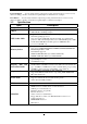
AMD K10 Processor Family Cooling Solutions As processor technology pushes to faster speeds and higher performance with increasing operation clock, thermal management becomes increasingly crucial while building computer systems. Maintaining the proper computing environment without thermal increasing is the key to reliable, stable, and 24 hours system operation. The overall goal is keeping the processor below its specified maximum case temperature.
Chapter 1 Introduction of AMD790GX Motherboards 1-1 Features of motherboard The AMD790GX chipset motherboard series are based on the latest AMD790GX Chipset and the SB750 chipset which supports the innovative 64-bit AMD Socket AM2+ dual core and quad core AMD Phenom™ processors and 64-bit AMD Socket AM2+/AM2 multi-tasking Socket AM2 Athlon64 X2 processors and Sempron Processors.
Embedded USB controllers as well as capability of expanding to 12 of USB2.0 functional ports delivering 480Mb/s bandwidth of rich connectivity, these motherboards meet the future USB demands which are also equipped with hardware monitor function on system to monitor and protect your system and maintain your non-stop business computing. Some special features--- CPU Thermal Throttling/ CPU Vcore 7-shift / CPU Smart Fan / DeBug Port /OC-CON (optional)/ DIY Clear / Power On Button/ Reset Button.
Power On Button… You can easily start the computer by pressing down this button for a few seconds, without troubling yourself to locate the front panel jumpers to find the Power on jumper. Reset Button..: You can easily restart the computer by pressing down this button for a few seconds, without troubling yourself to locate the front panel jumpers to find the reset jumper.
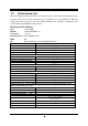
1-3 Performance List The following performance data list is the testing result of some popular benchmark testing programs. These data are just referred by users, and there is no responsibility for different testing data values gotten by users (the different Hardware & Software configuration will result in different benchmark testing results.
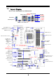
Layout Diagram 1-4 Rear I / O for AMD790GX based Motherboard Optional RJ-45 LAN DVI Connector ESATA Line-IN RS-OUT Line-OUT CS-OUT PS/2 Mouse PS/2 Keyboard SS-OUT USB HDMI VGA Connector MIC-IN USB ATX 12V Power Connector PS2 KB/Mouse Port CPUFAN SYSFAN2 Connector KBMB/USB Power On(JP1) HDMI Connector DDR2 Socket x 4 Optional E-SATA1 VGA and DVI Connector E-SATA Over USB Connector (CN1) RJ45 Over USB Connector (UL1) Audio Connector (J1) Optional 4-pin PWR Connector (HA07/HA07 Ultra) RTL8111C Gig
Jumpers Jumper JP1 JBAT Name Keyboard/USB Power On Enabled/Disabled Clear CMOS Header Description 3-pin Block 3-pin Block Page P.7 P.7 Name ATX Power Connector ATX 12V Power Connector PS/2 Mouse & PS/2 Keyboard Connector USB2.0 Port Connector Power Connector Gigabit LAN Port Connector 8-CH HD Audio Connector Floppy Driver Connector Primary IDE Connector Serial ATAII IDE Connectors Description 24-pin Block 8-pin Block 6-pin Female 4-pin Connector 4-Pin Block RJ-45 Connector 6- phone jack Conn.
Chapter 2 Hardware Installation WARNING! 2-1 Turn off your power when adding or removing expansion cards or other system components. Failure to do so may cause severe damage to both your motherboard and expansion cards. Hardware installation Steps Before using your computer, you had better complete the following steps: 1. Check motherboard jumper setting 2. Install CPU and Fan 3. Install System Memory (DIMM) 4. Install Expansion cards 5. Connect IDE and Front Panel /Back Panel cable 6.
3. After over clocking system boot fail JBAT JBAT 1-2 Closed Normal 2-3 Closed Clear CMOS CMOS RAM Clear Setting 2-3 Install CPU 2-3-1 Glossary Chipset (or core logic) - two or more integrated circuits which control the interfaces between the system processor, RAM, I/O devises, and adapter cards. Processor socket - the socket used to mount the system processor on the motherboard. Slot (PCI-E, PCI, RAM) - the slots used to mount adapter cards and system RAM.
2-3-2 About AMD Athlon64 Socket AM2+ CPU This motherboard provides a socket AM2+ surface mount, Zero Insertion Force (ZIF) socket, referred to as the mPGA940 socket supports AMD AM2+ processor in the 940 Pin package utilizes Flip-Chip Pin Grid Array package technology. The CPU that comes with the motherboard should have a cooling FAN attached to prevent overheating. If this is not the case, then purchase a correct cooling FAN before you turn on your system.
2-4 Install Memory This motherboard provides four 240-pin DDR2 DUAL INLINE MEMORY MODULES (DIMM) socket for DDR2 memory expansion available from minimum memory volume of 128MB to maximum memory volume of 8GB DDRII SDRAM.
2-5 Expansion Cards 2-5-1 Procedure For Expansion Card Installation 1. Read the documentation for your expansion card and make any necessary hardware or software setting for your expansion card such as jumpers. 2. Remove your computer’s cover and the bracket plate on the slot you intend to use. 3. Align the card’s connectors and press firmly. 4. Secure the card on the slot with the screen you remove above. 5. Replace the computer system’s cover. 6. Set up the BIOS if necessary. 7.
2-5-4 PCI Express Slot Two PCI-Express2.0 x16@8 lane graphic slot offer 4Gbyte/sec data transfer rate at each relative direction and up to 8Gbyte/sec concurrent bandwidth at full speed. Two x1 PCI Express Slot offer 1024Mbyte/sec concurrently over 7 times more bandwidth than PCI at 133Mbye/sec, tackling the most demanding multimedia tasks nowadays. Fully compliant to the PCI Express Base Specification revision2.0, support PCI Express VGA card, and other PCI Express device.
ROW1 ROW2 PIN ROW1 ROW2 Pin 1 Pin 1 20-Pin 24-Pin ROW1 ROW2 1 3.3V 3.3V 2 3.3V -12V 3 GND GND 4 5V Soft Power On 5 GND GND 6 5V GND 7 GND GND 8 Power OK -5V 9 +5V (for Soft Logic) +5V 10 +12V +5V 11 +12V +5V 12 +3V GND (2) ATX 12V Power Connector (8-pin block) : ATX12V This is a new defined 8-pins connector that usually comes with ATX Power Supply.
(7) Audio Line-In, Lin-Out, MIC, RS-Out, CS-Out,SS-Out connector : J1 These Connectors are 6 Phone-Jack for LINE-OUT, LINE-IN, MIC, RS-Out, CS-Out, SS-Out audio connections.
setting its jumpers accordingly. Please refer to the documentation of your hard disk for the jumper settings. IDE1 Pin 1 Primary IDE Connector • Two hard disks can be connected to each connector. The first HDD is referred to as the “Master” and the second HDD is referred to as the “Slave”. • For performance issues, we strongly suggest you don’t install a CD-ROM or DVD-ROM drive on the same IDE channel as a hard disk. Otherwise, the system performance on this channel may drop.
2-6-2 Headers AUDIO LINE2-JD MIC2-JD KEY Audio-GND Audio-JD (1) Line-Out/MIC Header for Front Panel (9-pin): AUDIO These headers connect to Front Panel Line-out, MIC connector with cable.
GND PWRBTN PWR LED VCC5 JW FP PWRLED PWRBTN PWRLED Pin 1 SPEAK RESET HDLED VCC5 VCC5 HDDLE GND RSTSW NC Pin 1 SPKR NC GND Pin 1 System Case Connections CPUFAN IN CPUFAN OUT GND +12V (8) FAN Power Headers: SYSFAN1, SYSFAN2, CHAFAN (3-pin), CPUFAN (4-pin) These connectors support cooling fans of 350mA (4.2 Watts) or less, depending on the fan manufacturer, the wire and plug may be different. The red wire should be positive, while the black should be ground.
IRRX GND IR 2 6 5 NC VCC5 IRTX Pin 1 IR infrared module Headers (11) Serial COM Port header: COM1 COM1 is the 9-pin block pin-header. The On-board serial port can be disabled through BIOS SETUP. Please refer to Chapter 3 “INTEGRATED PERIPHERALS SETUP” section for more detail information Pin1 Serial COM Port 9-pin Block (12) HDMI-SPDIF Out header: SPDIF Out The SPDIF output is capable of providing digital audio to external speakers or compressed AC3 data to an external Dolby digital decoder.
2-7 Starting Up Your Computer 1. After all connection are made, close your computer case cover. 2. Be sure all the switch are off, and check that the power supply input voltage is set to proper position, usually in-put voltage is 220V∼240V or 110V∼120V depending on your country’s voltage used. 3. Connect the power supply cord into the power supply located on the back of your system case according to your system user’s manual. 4. Turn on your peripheral as following order: a. Your monitor. b.
Chapter 3 Introducing BIOS The BIOS is a program located on a Flash Memory on the motherboard. This program is a bridge between motherboard and operating system. When you start the computer, the BIOS program will gain control. The BIOS first operates an auto-diagnostic test called POST (power on self test) for all the necessary hardware, it detects the entire hardware device and configures the parameters of the hardware synchronization.
3-3 The Main Menu Once you enter Award® BIOS CMOS Setup Utility, the Main Menu (Figure 3-1) will appear on the screen. The Main Menu allows you to select from fourteen setup functions and two exit choices. Use arrow keys to select among the items and press to accept or enter the sub-menu. .
This menu uses a minimal performance setting, but the system would run in a stable way. Load Optimized Defaults Use this menu to load the BIOS default values these are setting for optimal performances system operations for performance use. Password Settings This entry for setting Supervisor password and User password Save & Exit Setup Save CMOS value changes to CMOS and exit setup. Exit Without Saving Abandon all CMOS value changes and exit setup.
If the controller of HDD interface is SCSI, the selection shall be “None”. If the controller of HDD interface is CD-ROM, the selection shall be “None” Access Mode The settings are Auto Normal, Large, and LBA.
External Cache Choose Enabled or Disabled. This option enables the Level 2 cache memory. Quick Power On Self-Test This category speeds up Power On Self Test (POST) after you power on the computer. If this is set to Enabled, BIOS will shorten or skip some check items during POST. Enable quick POST Enabled (default) Normal POST Disabled First/Second/Third/Fourth Boot Device The BIOS attempts to load the operating system from the devices in the sequence selected in these items.
Allows OS2® to be used with >64MB or DRAM. Settings are Non-OS/2 (default) and OS2. Set to OS/2 if using more than 64MB and running OS/2®. 3-6 Advanced Chipset Features The Advanced Chipset Features Setup option is used to change the values of the chipset registers. These registers control most of the system options in the computer.
3-6-2 IGX Configuration Phoenix – AwardBIOS CMOS Setup Utility IGX Configuration Iternal Graphics Mode UMA frame Buffer Size Frame Buffer Location IGX Engine Clock OVERRIDE IGX Engine Clock Surround View IGX Clock Speek UMA-SP Inter leave Mode Size Ratio (SP:UMA) SP Power Management SB NB Termination SP ODT SP CMD Hold SP DATA Hold UMA+Side port Auto Above 4G Enabled 700 Auto 400MHz Auto 4MB 1:1 Auto Disabled Disabled Auto Auto Item Help Menu Level > ↑↓→← Move Enter:Select +/-/PU/PD:Value F10:Save ESC:E
3-7 Integrated Peripherals Phoenix – AwardBIOS CMOS Setup Utility Integrated Peripherals CMIX-SB750 Revision 2.5.
Line Printer port 1 (378H/IRQ7) Parallel Port Mode SPP : Standard Parallel Port EPP : Enhanced Parallel Port ECP : Extended Capability Port SPP/EPP/ECP/ECP+EPP To operate the onboard parallel port as Standard Parallel Port only, choose “SPP.” To operate the onboard parallel port in the EPP modes simultaneously, choose “EPP.” By choosing “ECP”, the onboard parallel port will operate in ECP mode only.
Ultra DMA/33 implementation is possible only if your IDE hard drive supports it and the operating environment includes a DMA driver (Windows 95 OSR2 or a third-party IDE bus master driver). If your hard drive and your system software both support Ultra DMA/33 and Ultra DMA/66, select Auto to enable BIOS support. The settings are: Auto, Disabled. IDE HDD Block Mode Block mode is also called block transfer, multiple commands, or multiple sector read/write.
3-8 Power Management Setup The Power Management Setup allows you to configure your system to most effectively save energy saving while operating in a manner consistent with your own style of computer use.
month), hour, minute and second to turn on your system. When set to 0 (zero) for the day of the month, the alarm will power on your system every day at the specified time . Date (of month) You can choose which month the system will boot up. Set to 0, to boot every day. Time (hh:mm:ss) You can choose what hour, minute and second the system will boot up. Note: If you have change the setting, you must let the system boot up until it goes to the operating system, before this function will work.
3-10 PC Health Status This section shows the Status of you CPU, Fan, and Warning for overall system status. is only available if there is Hardware Monitor onboard. This Phoenix – AwardBIOS CMOS Setup Utility PC Health Status Show PC Health in Post Shutdown Temperature smart FAN Configuration Vcc3.3 Vcore NBVCC +5V +12V 5VSB VDIMM CPU Temperature SYS Temperature CPUFAN Speed SYS FAN1 Speed SYS FAN2 Speed Enabled Disabled Press Enter 3.36V 1.35V 1.12V 4.85V 12.05V 12.05V 5.
3-11 Power User Overclock Setting Phoenix – AwardBIOS CMOS Setup Utility Power User Overclock Setting CPU Feature Press Enter CPU Clock At Next BOOT 200 PCIE Reference Clock Item Help [100] 【100】 SB Refence Clock Spread Spectrum Enabled CPU RATIO at Next BOOT Auto AOD Compatibility Disabled CPU Voltage At Next Boot Default CPU Vorce 7-Shift Normal VDIMM Select 1.95V NB Voltage Setting 1.15v NB-VDDHT Setting 1.
Phoenix – AwardBIOS CMOS Setup Utility CPU CPU Feature VCORE 7---SHIFT Item Help Press Enter CPU Clock At Next BOOT 200 PCIE Reference Clock [100] Menu Level > 【100】 SB Refence Clock Spread Spectrum Enabled CPU RATIO at Next BOOT Auto AOD Compatibility Disabled CPU Vcore 7-shift Normal +5% +10% CPU Voltage At Next Boot Default CPU Vorce 7-Shift Normal VDIMM Select 1.95V NB Voltage Setting 1.15v NB-VDDHT Setting 1.
This item allows you select the CPU Vcore Voltage xx% more than the standard value, by this function for the precise over-clocking for extra demanding of performance. NB Voltage This item allows you to select value of Voltage for North Bridge Chipset. IH Flow-Control Mode: Isochronous (ISOC) Flow Control Mode enable will make the HT Link communication have the complex ordering rules for Isochronous source to make sure it can get service from the system with deterministic worst-case latency.
3-11-1 CPU Feature Phoenix – AwardBIOS CMOS Setup Utility CPU Feature Virtualization AMD K8 Cool & Quiet control TLB Check Advanced clock calibration Value (ALL Cores) Value (Cores 0) Value (Cores 1) Value (Cores 2) Value (Cores 3) Enabled Disabled Enabled Disabled 2% 2% 2% 2% 2% Item Help Menu Level > ↑↓→← Move Enter:Select +/-/PU/PD:Value F10:Save ESC:Exit F1:General Help F5:Previous Values 3-11-2 F6:Fail-safe Defaults F7:Optimized Defaults DRAM Configuration Phoenix – AwardBIOS CMOS Setup Utili
This field let’s you insert a timing delay between the CAS and RAS strobe signals, used when DRAM is written to, read from, or refreshed. Fast gives faster performance; and Slow gives more stable performance. This field applies only when synchronous DRAM is installed in the system. Row Precharge Time If an insufficient number of cycles is allowed for the RAS to accumulate its charge before DRAM refresh, the refresh may be incomplete and the DRAM may fail to retain date.
center of the screen to assist you in creating a password. ENTER PASSWORD: Type the password, up to eight characters in length, and press . The password typed now will clear any previously entered password from CMOS memory. You will be asked to confirm the password. Type the password again and press . You may also press to abort the selection and not enter a password. To disable a password, just press when you are prompted to enter the password.
Chapter 4 DRIVER & FREE PROGRAM INSTALLATION Check your package and there is A MAGIC INSTALL CD included. This CD consists of all DRIVERS you need and some free application programs and utility programs. In addition, this CD also include an auto detect software which can tell you which hardware is installed, and which DRIVERS needed so that your system can function properly. We call this auto detect software MAGIC INSTALL.
4-1 Install ATI Driver Pack 1. Click ATI in the MAGIC INSTALL MENU appears. 2. Click NEXT when ATI software driver pack appears. 3. Click “Yes” to accept the license agreement and start installation.. 4. click “finish” * The path of the file is X:\ATI \DRIVER\SETUP.EXE NOTE: Please upgrade your Windows XP to Service Pack 1 / Windows 2000 to Service Pack 4 or later before you install the HD Audio CODEC driver 4-2 SOUND Install ALC888 HD Codec Audio Driver 1.
3. Click FINISH and restart your computer 4. Manual Sound Effect Setting 5. Devices and mixer setting 6. Audio input and output setting. 7. Microphone effect setting. 8. 3D demo setting. NOTE: Please upgrade your Windows XP to Service Pack 1 / Windows 2000 to Service Pack 4 or later before you the HD Audio CODEC driver.
4-3 LAN Install LAN 1 Click LAN when MAGIC INSTALL MENU appears 2. Click Next . 3 Click Install 2. Finish. 4-4 RAID Install ATI SATA Driver and Utility 1 Click RAIDDisk when MAGIC INSTALL MENU appears 2. 42 Install RAID Disk.
4-5 Install PC-CILLIN 2007 Anti-virus program 1 Click PC-CILLIN when MAGIC INSTALL MENU appears 2. 3. This is license agreement, select "I accept the terms in the license agreement" and Click NEXT. 4. . Click Next after you select the features you want to install and the folder to install it. 5 Click Install after you select to install the optional online services. Please select Next when the "Trend Micro internet security" install shield wizard windows appears 6.
4-6 PC-HEALTH Install MyGuard Hardware monitor Utility 1. Click PC-HEALTH when MAGIC INSTALL 2. Click Next on Install shield wizard Window MENU appears appears 3. Click Install to begin the installation. 4. Click Finish to complete the installation. NOTE: MAGIC INSTALL will auto detect file path X:\NF-ORCE4\MYGUARD\SETUP.EXE 4-7 HOW TO UPDATE BIOS STEP 1. Prepare a boot disc. (You may make one by click START click RUN type SYS A: click OK) STEP 2. Copy utility program to your boot disc.
4-8 AMD Platform RAID Function Installation Please set these choice in the BIOS as RAID:BIOS setup \Integrated Peripherals \Onchip SATA Device \ Onchip SATA Type. When the below figures appeared, please press [Ctrl-F] into figure 2 [figure1] Function: press[1] key, showing the RAID; press [2] key,building RAID; press [3] key, delete the RAID; press[4] key, showing the information of controller.
Press [2] key, the interface of RAID, as figure 4. RAID function: 1.RAID 1 2. RAID 0 3. RAID 10 4. JBOD [figure4] Choose LD 1 then press Enter. Take Raid0 for example, use [↑] [↓] to shift the cursor, press space key to change the choice, press [Ctrl-Y] to keep. Set Assignment mode as [Y], press [Ctrl-Y] to keep , then figure 5 appeared, erase the MBR. choose [Ctrl-Y],figure 6 appeared. Press any key, finished the RAID.
[figure6] Press [3], delete the RAID mode, as figure 7.press [Delete] will delete the array. As figure 7 . [figure7] Press [4], showing the information of controller, as figure 8.
Making RAID driver diskette before Install WindowsXP/2000 Before you install the Windows XP or Windows 2000, you will need to make a RAID driver diskette before you start to install the Operating System. How to make a RAID driver diskette? 1: Insert the diskette which is being formatted in floppy drive on a system which can start OS.
What functions does Pro Magic Plus have? 1. Instant System Restoration – Regardless of mis-operation or system crash, install Pro Magic Plus beforehand would allow you to instantly restore your system back by simply reboot your computer. 2. Easy-to-use – Auto installation from CD ROM; Supports Mouse 3. System Uninstall – Pro Magic provides a protection mode, which allows user to freely test any software.
◇ Minimum of 500MB free/usable space or above ◇ Support for SCSI & SATA Hard disk Pro Magic Plus only supports SCSI hard disk with Windows 2000 or OS above Notice Before Installation 1. Before install Pro Magic Plus, turn off all anti-virus software. (Include BIOS anti-virus function) 2. Pro Magic Plus does not support multiple PRI partitions. partitions, please repartition your HD before installation. If you have multiple PRI 3.
APPENDIX Debug Port Post Code Normal POST Codes NOTE: EISA POST codes are typically output to port address 300h. ISA POST codes are output to port address 80h. Code(hex) Name Description C0 Turn Off Chipset And CPU test C1 Memory Presence C2 Early Memory Initialization Extend Memory DRAM select OEM Specific-Cache control cache Processor Status (1FLAGS) Verification.
B Onboard Audio init C D E Reserved Reserved CheckSum Check F 10 Reserved Auto detec EEPROM 11 12 13 14 Reserved Cmos Check Reserved Chipset Default load Reserved Clock Init Reserved Identify the CPU Reserved Reserved Setup Interrupt Vector Table 15 16 17 18 19 1A 1B 1C 1D 1E 1F 20 21 22 23 Reserved Early PM Init Reserved Re-initial KB Reserved HPM init Reserved Test CMOS Interface and Battery Status 24 25 26 27 28 29 Reserved Reserved Reserved KBC final Init Reserved Initialize Video Interface
3C Test Timer Counter 2 3D 3E Reserved Test 8259-1 Mask Bits 3F 40 Reserved Test 8259-2 Mask Bits 41 42 43 Reserved Reserved Test Stuck8259's Interrupt Bits Test 8259 Interrupt Functionality Reserved Reserved Reserved Set EISA Mode 44 45 46 47 48 49 4A 4B 4C 4D 4E Reserved Size Base and Extended Memory Reserved Reserved Reserved Reserved Test Base and Extended Memory 4F 50 51 52 Reserved USB init Reserved Memory Test 53 54 55 Reserved Reserved CPU display 56 Reserved 57 58 59 5A 5B PnP Ini
vectors. 64 65 66 67 68 69 6A 6B 6C 6D 6E 6F 70 71 72 73 74 75 76 77 78 79 7A 7B 7C 7D 7E 7F 80 81 82 83 84 85 86 87 88 89 8A 8B 8C 8D 8E 8F 90 91 92 93 Reserved PS2 Mouse special Reserved ACPI init Reserved Setup Cache Controller Reserved Setup Entering Reserved Initialize Floppy Drive & Controller Reserved FDD install Special treatment to PS2 Mouse port ACPI sub-system initializing Initialize cache controller.
94 Final Init 95 Special KBC patch 96 Boot Attempt FF Boot Final init for last micro details before boot Set system speed for boot Setup NumLock status according to Setup Set low stack Boot via INT 19h.
70 Setup Init 71 72 Setup Cache Controller Install FDD 73 Install HDD 74 Detect & Initialize Math Coprocessor HDD Check for Write protection Reserved Display POST error 75 76 77 Display setup message and enable setup functions Detect if mouse is present, initialize mouse, install interrupt vectors. Special treatment to PS2 Mouse port ACPI sub-system initializing Initialize cache controller. Enter setup check and autoconfiguration check up Initialize floppy disk drive controller and any drives.
5B 5C Cmos Check Chipset default Prog 5D 5E Identify the CPU Setup Interrupt Vector Table 5F Test CMOS Interface and Battery status KBC final Init 60 61 Initialize Video Interface 62 Video memory test 63 Setup PS2 mouse and test DMA Test 8259 Init Boot Device 64 65 66 Install Boot Devices 67 68 69 Cache Init PM init PM final Init and issue SMI Full on FF Reset Video controller Keyboard controller init Test the Keyboard Initilized the mouse Check Cmos Circuitry and reset CMOS Program the ch
FF Boot Load boot sector 58