USER'S MANUAL Of AMD 790GX & AMD SB750 Based M/B For Socket AM2+ Quad Core AMD Processor NO. G03-MA379GDGCB-F Rev:1.0 Release date: January. 2009 Trademark: * Specifications and information contained in this documentation are furnished for information use only, and are subject to change at any time without notice, and should not be construed as a commitment by manufacturer.
Environmental Protection Announcement Do not dispose this electronic device into the trash while discarding. To minimize pollution and ensure environment protection of mother earth, please recycle.
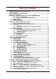
TABLE OF CONTENT SAFETY ENVIROMENTAL INSTRUCTION ....................................................................iii USER’S NOTICE.....................................................................................................................iv MANUAL REVISION INFORMATION ..............................................................................iv COOLING SOLUTIONS ........................................................................................................
APPENDIX .............. ........................................................................................................................ 46 Safety Environmental Instruction z Avoid the dusty, humidity and temperature extremes. Do not place the product in any area where it may become wet. z 0 to 40 centigrade is the suitable temperature.
USER’S NOTICE COPYRIGHT OF THIS MANUAL BELONGS TO THE MANUFACTURER. NO PART OF THIS MANUAL, INCLUDING THE PRODUCTS AND SOFTWARE DESCRIBED IN IT MAY BE REPRODUCED, TRANSMITTED OR TRANSLATED INTO ANY LANGUAGE IN ANY FORM OR BY ANY MEANS WITHOUT WRITTEN PERMISSION OF THE MANUFACTURER. THIS MANUAL CONTAINS ALL INFORMATION REQUIRED TO USE AMD 790GX MOTHERBOARD AND WE DO ASSURE THIS MANUAL MEETS USER’S REQUIREMENT BUT WILL CHANGE, CORRECT ANY TIME WITHOUT NOTICE.
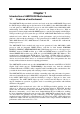
Chapter 1 Introduction of AMD790GX Motherboards 1-1 Features of motherboard The AMD790GX chipset motherboard series are based on the latest AMD790GX Chipset and the SB750 chipset which supports the innovative 64-bit AMD Socket AM3/AM2+AM2 dual core and quad core AMD Phenom™ processors and 64-bit AMD Socket AM3/AM2+/AM2 multi-tasking Socket AM2 Athlon64 X2 processors and Sempron Processors.
Embedded USB controllers as well as capability of expanding to 10 of USB2.0 functional ports delivering 480Mb/s bandwidth of rich connectivity, these motherboards meet the future USB demands which are also equipped with hardware monitor function on system to monitor and protect your system and maintain your non-stop business computing. Some special features--- CPU Thermal Throttling/ CPU Vcore 7-shift / CPU Smart Fan / OC-CON / G.P.I.
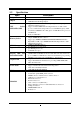
1-2 Specification Spec Design Description z z z z Gigabit LAN z z 8 CH-Audio z z z ATX form factor 4 layers PCB size:24.5cm x24.5cm AMD790GX North Bridge Chipset AMD SB750 South Bridge Chipset Support 64bit AMD Athlon64 940-Pin package utilizes Flip-Chip Pin Grid Array package processor Support for future AMD Athlon64 940-pin Dual –Core Athlon 64x2 processor, Athlon 64 & Sempron Processors with HTT Frequency 1GHz and the latest AMD Phenom™ FX, quad core AMD Phenom™ processors with HTT 3.0.
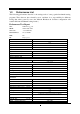
1-3 Performance List The following performance data list is the testing result of some popular benchmark testing programs. These data are just referred by users, and there is no responsibility for different testing data values gotten by users (the different Hardware & Software configuration will result in different benchmark testing results.
CPU: AMD AM3 925 DRAM: DDR III 1333 1GB*2 VGA Card: onboard(HD3300) Hard Disk Driver: ST sata 1000GB BIOS: T02 OS: winxp+sp3 (en) AMD 790GX 3D Mark 2003 5919 3D Mark 2005 4835 3D Mark 2006 2224 AQUAMRK3 50568 PCMark2005 System / CPU / Memory 6493/8520/4987 Graph / HDD 3043/6242 Content Creation Winstone 2004 49.5 Business Winstone 2004 32.5 Winbench 99 V2.
1-4 Layout Diagram Rear I / O for AMD790GX based Motherboard Coaxial SPDIF_OUT RJ-45 Connector VGA Connector ESATA Line-IN RS-OUT Line-OUT CS-OUT PS/2 Mouse PS/2 Keyboard SS-OUT HDMI USB Optical SPDIF_OUT DVI Connector MIC-IN USB KBMB/USB Power On(JP1) ATX 12V Power Connector CPUFAN PS2 KB/Mouse Port DDRIII Socket x 2 SPDIF_Out Connectors DDRII Socket x 2 HDMI Connector G.P.I.
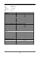
Jumpers Jumper JP1 JBAT Name Keyboard/USB Power On Enabled/Disabled Clear CMOS Header Description 3-pin Block 3-pin Block Page P.8 P.8 Name ATX Power Connector ATX 12V Power Connector PS/2 Mouse & PS/2 Keyboard Connector USB2.0 Port Connector Gigabit LAN Port Connector 8-CH HD Audio Connector Floppy Driver Connector Primary IDE Connector Serial ATAII Hard Disk Driver Connectors Description 24-pin Block 8-pin Block 6-pin Female 4-pin Connector RJ-45 Connector 6- phone jack Conn.
Chapter 2 Hardware Installation WARNING! 2-1 Turn off your power when adding or removing expansion cards or other system components. Failure to do so may cause severe damage to both your motherboard and expansion cards. Hardware installation Steps Before using your computer, you had better complete the following steps: 1. Check motherboard jumper setting 2. Install CPU and Fan 3. Install System Memory (DIMM) 4. Install Expansion cards 5. Connect IDE and Front Panel /Back Panel cable 6.
JBAT JBAT 1-2 Closed Normal 2-3 Closed Clear CMOS CMOS RAM Clear Setting 2-3 Install CPU 2-3-1 Glossary Chipset (or core logic) - two or more integrated circuits which control the interfaces between the system processor, RAM, I/O devises, and adapter cards. Processor socket - the socket used to mount the system processor on the motherboard. Slot (PCI-E, PCI, RAM) - the slots used to mount adapter cards and system RAM.
2-3-2 About AMD Athlon64 Socket AM2 CPU Socket This motherboard provides a socket AM2 surface mount, Zero Insertion Force (ZIF) socket, referred to as the mPGA940 socket supports AM3/ AM2+/AM2 AMD processor utilizes Flip-Chip Pin Grid Array package technology. The CPU that comes with the motherboard should have a cooling FAN attached to prevent overheating. If this is not the case, then purchase a correct cooling FAN before you turn on your system.
2-4 Install Memory This motherboard provides two 240-pin DDR II DUAL INLINE MEMORY MODULES (DIMM) socket for DDR II memory SDRAM expansion available from minimum memory volume of 128MB to maximum memory volume of 4 GB and two 240-pin DDR III SDRAM DUAL INLINE MEMORY MODULES (DIMM) socket for DDR III memory expansion available from minimum memory volume of 128MB to maximum memory volume of 4 GB.
NOTICE! When you install DIMM module fully into the DIMM socket the eject tab should be locked into the DIMM module very firmly and fit into its indention on both sides. WARNING! This motherboard only supports DDR II 667/800 or higher frequency- compliant DDR II Modules in DDRII memory slots and DDR III 1066 or higher frequency-compliant DDR III Modules in DDRIII memory slots. 2-5 Expansion Cards 2-5-1 Procedure For Expansion Card Installation 1.
2-5-3 PCI Express Slot Two PCI-Express2.0 x16@8 lane graphic slot offer 4Gbyte/sec data transfer rate at each relative direction and up to 8Gbyte/sec concurrent bandwidth at full speed, fully compliant to the PCI Express Base Specification revision2.0, support PCI Express VGA card, and other PCI Express device. This motherboard support Hybrid CrossFireX function. One x1 PCI Express 1.0 a Slot offer 512 Mbyte/sec concurrently over 3.
2-6 Connectors, Headers 2-6-1 Connectors (1) Power Connector (24-pin block) : ATXPWR1 ATX Power Supply connector: This is a new defined 24-pins connector that usually comes with ATX case. The ATX Power Supply allows using soft power on momentary switch that connect from the front panel switch to 2-pins Power On jumper pole on the motherboard.
(3) PS/2 Mouse & PS/2 Keyboard Connector: KB The connectors are for PS/2 keyboard and PS/2 Mouse. (4) USB Port connector: CN5/ UL1 for USB The connectors are 4-pin connector that connects USB devices to the system board. (5) LAN Port connector: UL1 for RJ45 LAN The connector is standard RJ45 connector for Network.
IDE1 Pin 1 Primary IDE Connector • Two hard disks can be connected to each connector. The first HDD is referred to as the “Master” and the second HDD is referred to as the “Slave”. • For performance issues, we strongly suggest you don’t install a CD-ROM or DVD-ROM drive on the same IDE channel as a hard disk. Otherwise, the system performance on this channel may drop.
(14)Coaxial SPDIF_OUT and optical SPDIF_OUT connectors: SPDIF_OUT1/ SPDIF_OUT2 The SPDIF output is capable of providing digital audio to external speakers or compressed AC3 data to an external Dolby digital decoder. Use this feature only when your stereo system has digital input function. The board has coaxial and optical SPDIF_OUT connectors.
JW FP PWRBTN GND PWRLED Pin 1 PWRLED PWRBTN VCC5 PWR LED (7) Power switch: PWR BTN This 2-pin connector connects to the case-mounted power switch to power ON/OFF the system. SPEAK RESET HDLED VCC5 VCC5 HDDLE GND RSTSW NC Pin 1 SPKR NC GND Pin 1 System Case Connections CPUFAN IN CPUFAN OUT GND +12V (8) FAN Power Headers: SYSFAN1, SYSFAN2 (3-pin), CPUFAN (4-pin) These connectors support cooling fans of 350mA (4.
GND IR IRRX (10) IR infrared module Headers (5-pin): IR1 This connector supports the optional wireless transmitting and receiving infrared module. You must configure the setting through the BIOS setup to use the IR function. 2 6 5 NC VCC5 IRTX Pin 1 IR infrared module Headers (11) Serial COM Port header: COM1 COM1 is the 9-pin block pin-header. The On-board serial port can be disabled through BIOS SETUP. Please refer to Chapter 3 “INTEGRATED PERIPHERALS SETUP” section for more detail information.
2-7 Starting Up Your Computer 1. After all connection are made, close your computer case cover. 2. Be sure all the switch are off, and check that the power supply input voltage is set to proper position, usually in-put voltage is 220V∼240V or 110V∼120V depending on your country’s voltage used. 3. Connect the power supply cord into the power supply located on the back of your system case according to your system user’s manual. 4. Turn on your peripheral as following order: a. Your monitor. b.
Chapter 3 Introducing BIOS The BIOS is a program located on a Flash Memory on the motherboard. This program is a bridge between motherboard and operating system. When you start the computer, the BIOS program will gain control. The BIOS first operates an auto-diagnostic test called POST (power on self test) for all the necessary hardware, it detects the entire hardware device and configures the parameters of the hardware synchronization.
3-3 The Main Menu Once you enter AMI BIOS Setup Utility, the Main Menu (Figure 3-1) will appear on the screen. The Main Menu allows you to select from 12 setup functions and 2 exit choices. Use arrow keys to select among the items and press to accept or enter the sub-menu. CMOS Setup Utility-Copyright(C)1985-2005 American Megatrends. Inc.
Load Failsafe Defaults This menu uses a minimal performance setting, but the system would run in a stable way. Load Optimized Defaults Use this menu to load the BIOS default values these are setting for optimal performances system operations for performance use. Password Settings This entry for setting Supervisor password and User password Save & Exit Setup Save CMOS value changes to CMOS and exit setup. Exit Without Saving Abandon all CMOS value changes and exit setup.
System Time The time format is . Primary IDE Master / Slave SATA Channel 1, 2, 3, 4, 5, 6 While entering setup, BIOS auto detest the presence of IDE devices. This displays the status of auto detection of IDE devices. Type: The optional settings are: Not Installed; Auto; CD/DVD and ARMD LBA/Large Mode: The optional settings are Auto; Disabled. Block (Multi-Sector Transfer): The optional settings are: Disabled and Auto. PIO Mode: the optional settings are: Auto, 0, 1, 2, 3 and 4.
Removable Drives Use this item to specify the boot device priority sequence from available removable drives. Quick Boot Allows BIOS to skip certain tests while booting. This will decrease the needed to boot the system. 1st Boot Device Specify the boot sequence from the available devices. A device enclosed in parenthesis has been disabled in corresponding type menu. Boot Up NumLock Status The default value is On. On (default) Keypad is numeric keys. Keypad is arrow keys.
3-6-1 Memory Configuration CMOS Setup Utility-Copyright(C)1985-2005 American Megatrends. Inc. Memory Configuration DRAM Timing Mode Memory CLK: CAS Latency (Tcl): RAS/CAS Delay(Trcd): Row Precharge Time(Trp): Min Active RAS(Trrd): Row Cycle(Trc) Write Recover Time(Twr) Bank Interleaving Enabled clock to AC1 DIMMs Mem CLK Tristate C3/ATL VID Memory Hole Remapping DCI Unganged Mode Power Down Enabled Power Down Mode Auto 400MHz 5.
3-6-2 Internal Graphics Configurations CMOS Setup Utility-Copyright(C)1985-2005 American Megatrends. Inc.
3-7 Integrated Peripherals CMOS Setup Utility-Copyright(C)1985-2005 American Megatrends. Inc. Integrated Peripherals Onboard SATA Device Onboard Device Control Super IO Configuration Press Enter Press Enter Press Enter Help Item ↑↓→← Move Enter: Select +/-/PU/PD: Value F10:Save ESC: Exit F1:General Help F5:Previous Values F6:Optimized Defaults F7:Standard Defaults 3-7-1 Onboard SATA Device CMOS Setup Utility-Copyright(C)1985-2005 American Megatrends. Inc.
Press Enter to set values for sub-items as: Legacy USB Support, USB 2.0 Controller Mode BIOS EHCI Hand-OFF. 3-7-3 Super IO Configuration CMOS Setup Utility-Copyright(C)1985-2005 American Megatrends. Inc.
Restore on AC Power Loss The optional settings are: Disabled; Power on; Power Off and last state. 3-9 Miscellaneous Control CMOS Setup Utility-Copyright(C)1985-2005 American Megatrends. Inc.
3-10 PC Health Status This section shows the Status of you CPU, Fan, and Warning for overall system status. is only available if there is Hardware Monitor onboard. This CMOS Setup Utility-Copyright(C)1985-2005 American Megatrends. Inc. PC Health Status PC Health Status Smart FAN Configuration H/W Health Function CPU Temperature: System Temperature: CPUFAN Speed: SYSFAN1 Speed: SYSFAN Speed: NB1.2V : VDIMM : VCORE: NBPCIE: Help Item Press Enter Enabled 50°C/122°F 60°C/140°F 2923RPM N/A N/A 1.160V 2.
3-11 Thermal Throttling Options CMOS Setup Utility-Copyright(C)1985-2005 American Megatrends. Inc. Thermal Throttling Options Help Item CPU Thermal-Throttling CPU Throttling Temp CPU Throttling Duty Enabled 70°C 50% Options Disabled Enabled ↑↓→← Move Enter:Select +/-/PU/PD:Value F10:Save ESC:Exit F1:General Help F5:Previous Values F6:Optimized Defaults F7:Standard Defaults CPU Thermal Throttling Use this item to enable or disable CPU thermal Throttling. The optional settings are: Enable; Disabled.
PCI E Reference Clock The optional setting range is:90~250 MHz. SB Reference Clock The optional setting range is:90~150 MHz. Spread Spectrum The optional settings are: Disabled; SRC CLK; CPUHT CLK and All CLK. Processor Voltage The optional settings are: Auto; 0.800V~1.350V. AOD Compatibility Choose Enabled means only AMD over drive can adjust voltage Choose Disabled means only BIOS can adjust voltage CPU Vcore 7-Shift Use this item to set value in CPU Vcore 7-Shift function.
A message will confirm that the password will be disabled. Once the password is disabled, the system will boot and you can enter Setup freely. PASSWORD DISABLED. When a password has been enabled, you will be prompted to enter it every time you try to enter Setup. This prevents an unauthorized person from changing any part of your system configuration. Additionally, when a password is enabled, you can also require the BIOS to request a password every time your system is rebooted.
Chapter 4 Driver & Free Program Installation Check your package and there is A MAGIC INSTALL CD included. This CD consists of all DRIVERS you need and some free application programs and utility programs. In addition, this CD also include an auto detect software which can tell you which hardware is installed, and which DRIVERS needed so that your system can function properly. We call this auto detect software MAGIC INSTALL. Magic Install supports Windows 9X/ME/ NT4.
4-1 ATI Install ATI Driver Pack 1. Click ATI when the MAGIC INSTALL MENU appears. 2. Click NEXT when ATI software driver pack appears. 3. Click “Yes” to accept the license agreement and start installation.. 4. Click Express, recommended. 5. Click Continue Anyway. 6. Finish the installing. * The path of the file is X:\ATI \DRIVER\SETUP.
4-2 SOUND Install ALC883 HD Audio Codec Driver 1. Click SOUND when MAGIC INSTALL MENU appears 2. Click NEXT When Realtek High Definition Audio driver windows appear 3. Click FINISH and restart your computer 4. 5. Devices and mixer setting 6. Audio input and output setting. 7. Microphone effect setting. 8. 37 Manual Sound Effect Setting 3D demo setting.
NOTE: Please upgrade your Windows XP to Service Pack 1 / Windows 2000 to Service Pack 4 or later before you the HD Audio CODEC driver. 4-3 LAN Install LAN 1 Click LAN when MAGIC INSTALL MENU appears 2. Click Next . 3 Click Install 2. Finish. 4-4 RAID Install ATI SATA Driver and Utility 1 Click RAIDDisk when MAGIC INSTALL MENU appears 2. 38 Install RAID Disk.
4-5 Norton Install Norton 2009 Anti-virus program 1 Click NORTON when MAGIC INSTALL MENU appears 4-6 PC-Health 2. Please select Agree&install. Install MyGuard Hardware Monitor Utility 1. Click PC-HEALTH when MAGIC INSTALL 2. Click Next on Install shield wizard Window MENU appears appears 3. Click Install to begin the installation. 4. Click Finish to complete the installation. NOTE: MAGIC INSTALL will auto detect file path X:\NF-ORCE4\MYGUARD\SETUP.
4-7 OVER CLOCK Install OVERCLOCK Drive Utility 1. Click OVER CLOCK when MAGIC INSTALL MENU appears 2. Click Next 3. Choose “I accept the terms in the license agreement”. 4. The information describe the installation, Click Next 5. Choose “Anyone who use this computer” Click Next. 6. Choose Yes and Next.
7. Ready to install the program, click Install. 8. Finish the installation. 4-7 How to Update BIOS STEP 1. Prepare a boot disc. (You may make one by click START click RUN type SYS A: click OK) STEP 2. Copy utility program to your boot disc. You may copy from DRIVER CD X:\FLASH\AWDFLASH.EXE or download from our web site. STEP 3. Download and make a copy of the latest BIOS for 770 SERIES motherboard series from the web site to your boot disc. STEP 4.
[figure1] Function: press[1] key, showing the RAID; press [2] key,building RAID; press [3] key, delete the RAID; press[4] key, showing the information of controller. [figure2] press[1] key,showing the RAID,as the below figure [figure3] Press [2] key, the interface of RAID, as figure 4. RAID function: 1.RAID 1 2. RAID 0 42 3. RAID 10 4. RAID 5 5.
[figure4] Choose LD 1 then press Enter. Take Raid0 for example, use [↑] [↓] to shift the cursor, press space key to change the choice, press [Ctrl-Y] to keep. Set Assignment mode as [Y], press [Ctrl-Y] to keep , then figure 5 appeared, erase the MBR. choose [Ctrl-Y],figure 6 appeared. Press any key, finished the RAID.
[figure6] Press [3], delete the RAID mode, as figure 7.press [Delete] will delete the array. As figure 7 . [figure7] Press [4], showing the information of controller, as figure 8. [figure8] Making RAID driver diskette before Install WindowsXP/2000 Before you install the Windows XP or Windows 2000, you will need to make a RAID driver diskette before you start to install the Operating System.
2000 CD into the CD-ROM drive. Then remove the floppy diskette, and boot the system. At the very beginning, you will see the message at the bottom of screen, “Press F6 if you need to install a third party SCSI or RAID driver….” At this moment, please press key and follow the instructions of Windows XP or Windows 2000 for the proper installation. Execute Start Æ programs Æ NVIDIA corporation Æ RAID manager , you can view RAID function status or rebuild RAID function from Windows OS 4-9 G.P.I.
Subject 1: Supply Mold APPENDIX Regarding the Application of 3-Phase or 3+1 Phase Power As a result of the increasing power consumption demand from many AMD CPUs in current market, we suggest not to use a CPU that demands more than 65W power consumption at work for an AMD CPU compliant board that comes with power supply design as 3 phase or 3+1 phase mold and MOSFET design as working in High SideX1 and Low SideX1 mold so as to avoid MOSFET getting burned or other phenomena like a halted system or system i
Figure 2 Solution: We recommend users choose motherboards with power design of 4-phase, 4+1 phase or more for CPUs that demand 89W or 95W power consumption. We recommend users choose motherboards with power design of 5-phase, 5+1 phase or more for CPUs that demand 125W or 140W power consumption. Subject 2: Suggestion on choosing electric fan Both the amount of electric current to MOSFET and the heat produced from the motherboard go up as AMD’s CPU power consumption increases.
Figure 1---- CPU Fan can not blow off the heat produced by MOSFET. We suggest not to using fans of this kind Cool air flowing i Hot air flowing out Figure 2---- CPU Fan can blow off the heat produced by MOSFET.