
Specifications

©
2008 Advanced Micro Devices Inc.
Serial ATA (SATA)
AMD SB600 BIOS Developer’s Guide (Public Version) Proprietary
Page 30
7 Serial ATA (SATA)
The SB600 has two SATA devices. For ASIC revision A21, they are at Bus 0, Device 12h,
Function 0 and Bus 0, Device 11h, Function 0. For revisions A11 and A12, they are at Bus 0,
Device 13h, Function 3 and Function 4. The SATA devices are enabled/disabled through a
register at ADh in the SMBus controller (Device 14h, function 0).
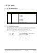
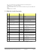
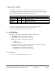
MiscSata - RW - 8 bits - [PCI_Reg: ADh]
Field Name Bits Default Description
SATA Enable 0 1 SATA enable
SataSmbusEn 1 0 SATA SMBus enable
SataSmbusMode 2 0 SATA SMBus mode, set to 1 to put SATA I2C on GPIO pins
SataPsvEn
Enable
5 1 SATA power saving enable
MiscSata register
The SATA option ROM initial load size is 64KB, and the run time size is 2KB.
A SATA controller enable/disable sample code is found in section 14.2.5.
A SATA class ID change sample code is found in section 14.2.6.
7.1 SATA Hot Plug
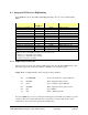
The SATA hot plug feature is implemented through the following registers:
1. ACPI GPE0 Block status register bit 31 for SCI status.
2. ACPI GPE0 Block enable register bit 31 for SCI enable.
3. PMIO register 37h bit 2 to trigger SATA hot plug SCI.
1 = Rising edge.
0 = Falling edge trigger.
4. The SATA internal status is set whenever a SATA hard drive is plugged in, unplugged,
powered up, or powered down. The status registers are:
Register BAR 5 + 10Ah, bit 0, for primary channel.
Register BAR 5 + 18Ah, bit 0, for secondary channel.
7.1.1 Sample Code
See section 14.7 for the SATA Hot Plug sample code.