N2PA-LITE / N2PAP-LITE USER'S MANUAL AMD Athlon XP/Athlon/Duron Processor M/B NO. G03-N2PALITE1A Release date: August 2003 Remark: * Specifications and information contained in this manual are furnished for information use only, and are subject to change at any time without notice, and shall not be construed as a commitment by manufacturer.
TABLE OF CONTENT USER’S NOTICE............................................................................................................ii MANUAL REVISION INFORMATION ..........................................................................ii COOLING SOLUTIONS ...............................................................................................ii CHAPTER 1 INTRODUCTION OF N2PA-LITE/N2PAP-LITE MOTHERBOARD 1-1 FEATURE OF MOTHERBOARD........................................................
USER’S NOTICE COPYRIGHT OF THIS MANUAL IS RESERVED BY THE MANUFACTURER. NO PART OF THIS MANUAL, INCLUDING THE PRODUCTS AND SOFTWARE DESCRIBED IN IT MAY BE REPRODUCED, TRANSMITTED OR TRANSLATED INTO ANY LANGUAGE IN ANY FORM OR BY ANY MEANS WITHOUT WRITTEN PERMISSION OF THE MANUFACTURER. THIS MANUAL CONTAINS ALL INFORMATION REQUIRED TO USE THE N2PA-LITE/N2PAP-LITE MOTHERBOARD. THE CONTENTS ARE SUBJECT TO CHANGE FROM TIME TO TIME WITHOUT PRIOR NOTICE.
Chapter 1 Introduction of N2PA-LITE/N2PAP-LITE Motherboard 1-1 Features of Motherboard The all new N2PA-LITE and N2PAP-LITE is the latest desktop motherboard solution incorporating support for the new AMD Athlon™ XP processor 3200+ with advanced 400MHz front side bus technology (FSB) and DDR400 memory modules. It brings the power and performance of NVIDIA nForce2 technology to the mainstream market with more features and functionality.
1-2 Specifications Spec Design Chipset Description ∗ ∗ ∗ CPU Socket ∗ ∗ ∗ ∗ Expansion Slot & Headers Integrated IDE ∗ ∗ ∗ ∗ ∗ ∗ ∗ 6 Channel Audio ∗ Memory Socket BIOS Onboard LAN (for N2PAP-LITE) Multi I/O ∗ ∗ ∗ ∗ ∗ ∗ ∗ ∗ ∗ ATX form factor 4 layers PCB size: 30.5x19.0cm nVIDIA nForce2 400 System Platform Processor (400) north bridge nVIDIA nForce2 Media and Communications Processor (MCP) south bridge Support AMD Athlon 1.1GHz∼1.4GHz processor Support AMD Duron 900MHz∼1.
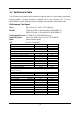
1-3 Performance Table The following performance table indicates the testing results of some popular benchmark testing programs. The data provided is intended just for user reference only. You may obtain different results depending upon the hardware and software configuration used.
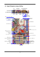
1-4 Layout Diagram & Jumper Setting LAN PRINTER GAME/MIDI PORT PS/2 MOUSE PS/2 KEYBOARD USB COM1 COM2A K/B Power ON Jumper (JP1) MIC LINE-IN LINE-OUT CPU Socket CPU FAN PS2 KB/Mouse Port USB Port/ LAN Connector DDR DIMM X2 PC99 Back Panel nVIDIA nForce2 400 Chip (JP2) CPU F.S.B. Frequency Selector ATX Power Connector Front Panel Audio CD Audio SFAN1 AC97’ Audio Codec AGP 4X/8X Slot nVIDIA nForce2 MCP Chip CIR Connector Winbond 83627HF Chip ATA 133 IDE Conn.
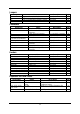
Jumpers Jumper JP1 JP4 JP2 JP3 Name Keyboard Power On Enabled/Disabled USB Wake-Up Enabled/Disabled CPU Front Side Bus Frequency Selector CMOS RAM Clear Jumper Description 3-pin Block 3-pin Block 2-pin Block 3-pin Block Page P.6 P.6 P.6 P.7 Name ATX Power Connector PS/2 Mouse & PS/2 Keyboard Connector USB/LAN Port Connector Parallel Port Connector Audio Connector Description 20-pin Block 6-pin Female Page P.12 P.12 2 x 4-pin/RJ45 Connector 25-pin Female 3 phone jack Connector P.12 P.13 P.
Chapter 2 Hardware Installation 2-1 Hardware installation Steps When installing the system, make sure to follow steps described in below: 1. Check motherboard setting 2. Install CPU 3. Install memory 4. Install expansion cards 5. Connect ribbon cables, panel wires, and power supply 6. Setup BIOS 7.
Note: CPU Front Side Bus Frequency also can be changed in BIOS SETUP. Please refer to page 32 “Host Clock at Next Boot Is” selection in Miscellaneous Control menu. Note: When the overclocking causes system boot failure, you will need to hold the “INS” key and the power on button at the same time until the screen resumes display to the standard default. Otherwise the CMOS will keep the faulty data and the motherboard will not function.
2-3 Install CPU 2-3-1 Glossary Chipset (or core logic) - two or more integrated circuits which control the interfaces between the system processor, RAM, I/O devises, and adapter cards. Processor Slot/Socket - the slot or socket used to mount the system processor on the motherboard. Slot (AGP, PCI, ISA, RAM) - the slots used to mount adapter cards and system RAM. AGP - Accelerated Graphics Port - a high speed interface for video cards; runs at 1X (66MHz), 2X (133MHz), 4X (266MHz), or 8X (533MHz).
Overheat Protect: Only for Athlon XP series CPU, when the CPU is overheated, system will automatically shut down power supply. You can hear a continue beep sound, the power button will be locked up. You must turn off and turn on the AC power to reset the system. Otherwise, the power button will not function. The other way is to keep pressing the button for a few seconds till the beep sound stops. Then, release the power button and press the power button again to turn on the power supply.
DIMM2 (BANK2+BANK3) DIMM1 (BANK0+BANK1) Figure 2-4 NOTE! When you install DIMM module fully into the DIMM socket the eject tab should be locked into the DIMM module very firmly and fit into its indention on both sides. WARNING! For the DDR SDRAM CLOCK setting of 166MHz, use only DDR333 compliant DDR Modules.
Standard Interrupt Assignments IRQ 0 1 2 3* 4* 5* 6* 7* 8 9* 10 * 11 * 12 * 13 14 * 15 * Priority N/A N/A N/A 8 9 6 11 7 N/A 10 3 2 4 N/A 5 1 Standard function System Timer Keyboard Controller Programmable Interrupt Communications Port (COM2) Communications Port (COM1) Sound Card (sometimes LPT2) Floppy Disk Controller Printer Port (LPT1) System CMOS/Real Time Clock ACPI Mode when enabled IRQ Holder for PCI Steering IRQ Holder for PCI Steering PS/2 Compatible Mouse Port Numeric Data Processor Primary IDE
2-5-4 AGP Slot The motherboard provides an AGP Slot, supporting the 4X/8X AGP VGA card. AGP SLOT 2-6 Connectors, Headers 2-6-1 Connectors (1) Power Connector (20-pin block) : PWR ATX power supply connector. This is a newly defined 20-pins connector that usually comes with ATX case. The ATX power supply allows the use of soft power on momentary switch that connects from the front panel switch to 2-pins power-on jumper pole on the motherboard.
(5) Parallel Port Connector (25-pin female): LPT Parallel port connector is a 25-pin D-subminiature receptacle connector. The onboard parallel port can be disabled through the BIOS SETUP. Please refer to Chapter 3 “INTEGRATED PERIPHERALS SETUP” section for more detail information. (6) Audio Connector : AUDIO_PORT/AUDIO_GAME Audio port uses a connector with 3 phone jacks for LINE-OUT, LINE-IN and MIC.
(9) Primary IDE Connector (40-pin block): IDE1 This connector is for IDE hard disk ribbon cable connection. Connect the single plug end to motherboard and the two plugs at other end to your hard disk(s). If you install two hard disks, you must configure the second drive to Slave mode by setting its jumpers accordingly. Please refer to the documentation of your hard disk for the jumper settings.
+DATA GND OC VCC -DATA VCC +DATA GND -DATA +DATA GND Pin 1 VCC Pin 1 USB1 -DATA +DATA GND OC USB2 VCC USB Port Header (9-pin) : USB1/USB2 The headers are used for connecting the additional USB device. With an option USB cable, your can have two additional USB plugs affixed to the back panel. -DATA (2) USB Port Headers (4) Reset switch lead: RESET This 2-pin connector connects to the case-mounted reset switch for rebooting your computer without having to turn off your power switch.
(8) Wake On-LAN Headers (3-pin) : WOL This connector connects to LAN card with WAKE ON-LAN output. When connected, a wake up signal received through the LAN card will power up the system. 5VSB GND WOL NOTE: This feature requires the Wake On LAN or Ring In Wake Up be enabled. WOL 1 3 Wake-On-LAN Headers (9) FAN Speed Headers (3-pin) : SFAN1, SFAN2, CPUFAN These connectors support a ≦350mA (4.2 Watts) current to cooling fans. Depending on the fan manufacturer, the wire and plug may be different.
GND IRRX IR 2 6 Pin 1 NC VCC IRTX 5 IR infrared module Headers (11) CD Audio-In Headers (4-pin) : CDIN CDIN is the connector for CD-Audio input signal. It connects to the CD-ROM CDAudio output connector.
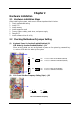
2-7 Starting Up Your Computer 1. After all connections are made, close your computer case cover. 2. Be sure all the switches are off and the power supply input voltage is set to proper position. The input voltage is either 220V∼240V or 110V∼120V depending on your country’s power voltage. 3. Plug the power supply cord into the power socket located on the back of your system case according to your system user’s manual. 4. Turn on your peripherals in following order: a. Your monitor. b.
Chapter 3 Introducing BIOS The BIOS is a program stored in a flash memory on the motherboard. The program serves as a bridge between motherboard and operating system. When you switch on the system, the BIOS program gains immediate control. The BIOS first executes an auto-diagnostic test called POST (power on self test) on all the necessary hardware. It detects the entire hardware devices and configures the parameters of the hardware for synchronization.
3-3 The Main Menu Once you enter Award® BIOS CMOS Setup Utility, the Main Menu (Figure 3-1) will appear on the screen. There are fourteen setup functions and two exit choices allowing you to select under the Main Menu. Use arrow keys to select among the items and press to accept or enter the sub-menu.
Load Optimized Defaults Use this menu to load the BIOS default values that are factory-set for optimal system performances operation. Load Standard Defaults Use this menu to load the BIOS default values for the minimal/stable performance system operation. Set Supervisor/User Password Use this menu to set User and Supervisor Passwords. Save & Exit Setup Save changes of CMOS value to CMOS and exit setup. Exit Without Saving Abandon all CMOS values changed and exit setup.
Time The time format is . Primary Master/Primary Slave Secondary Master/Secondary Slave Press PgUp/<+> or PgDn/<–> to select Manual, None, Auto type. Note that the specifications of your drive must match with the drive table. The hard disk will not work properly if you enter improper information for this category. If your hard disk drive type is not matched or listed, you can use Manual to define your own drive type manually.
Anti-Virus Protection Allows you to choose the VIRUS Warning feature for IDE Hard Disk boot sector protection. If this function is enabled and someone attempt to write data into this area, BIOS will prompt a warning message on screen and give beep sound. Disabled (default) No warning message will appear when attempts are there to access the boot sector or hard disk partition table.
Typematic Rate (Chars/Sec) Sets the number of times in a second to repeat a keystroke when you hold the key down. The settings are: 6, 8, 10, 12, 15, 20, 24, and 30. Typematic Delay (Msec) Sets the delay time after the key is held before it begins to repeat the keystroke. The settings are 250, 500, 750, and 1000. Security Option This category allows you to limit the access to the system and Setup, or just to Setup.
CAS Latency When synchronous DRAM is installed, the number of clock cycles of CAS latency depends on the DRAM timing. The settings are: 2T and 2.5T. System BIOS Cacheable Selecting Enabled allows caching of the system BIOS ROM at F0000h-FFFFFh, resulting in better system performance. However, if any program writes to this memory area, a system error may result. The settings are: Enabled and Disabled. Video RAM Cacheable Select Enabled allows caching of the video BIOS, resulting in better system performance.
3-7-1 Onboard IDE Function CMOS Setup Utility – Copyright(C) 1984-2003 Award Software OnChip IDE Function OnChip IDE Channel0 OnChip IDE Channel1 Primary Master PIO Primary Slave PIO Secondary Master PIO Secondary Slave PIO Primary Master UDMA Primary Slave UDMA Secondary Master UDMA Secondary Slave UDMA IDE 32-bit Transfer Mode IDE HDD Block Mode IDE Prefetch Mode Delay For HDD (Secs) Enabled Enabled Auto Auto Auto Auto Auto Auto Auto Auto Enabled Enabled Enabled 0 Item Help Menu Level >> ↑↓→← Move Ent
3-7-2 Onboard Device Function CMOS Setup Utility – Copyright(C) 1984-2003 Award Software OnChip Device Function AC97 Sound Device Game Port Address Midi Port Address X Midi Port IRQ nVIDIA LAN Function USB Host Controller USB 2.
Onboard FDD Controller Select Enabled if your system has a floppy disk controller (FDD) installed on the system board and you wish to use it. If you install add-on FDC or the system has no floppy drive, select Disabled in this field. The settings are: Enabled and Disabled. Onboard Serial Port 1/Port 2 Select an address and corresponding interrupt for the first and the second serial ports. The settings are: 3F8/IRQ4, 2E8/IRQ3, 3E8/IRQ4, 2F8/IRQ3, Disabled, Auto.
This item allows you to Enabled/Disabled the Advanced Configuration and Power Management (ACPI). The settings are Enabled and Disabled. Video Off Method This determines the manner in which the monitor is blanked. DPMS (default) Initial display power management signaling. Blank Screen This option only writes blanks to the video buffer. V/H SYNC+Blank This selection will cause the system to turn off the vertical and horizontal synchronization ports and write blanks to the video buffer.
Normally, this field is set Disabled. If you have installed a new add-on and the system reconfiguration has caused a serious conflict resulting in the operating system boot failure, select Enabled to reset Extended System Configuration Data (ESCD) when you exit Setup. The settings are: Enabled and Disabled. Resource Controlled By The Award Plug and Play BIOS has the capability to configure all of the boot and Plug and Play compatible devices automatically.
3-10 PC Health Status This section shows the Status of you CPU, Fan, Warning for overall system status. This is only available if there is Hardware Monitor onboard. CMOS Setup Utility – Copyright(C) 1984-2003 Award Software PC Health Status Shutdown Temperature Show PC Health in Post Current System Temperature Current CPU Temperature Current CPUFAN Speed Current SYSFAN1 Speed Current SYSFAN2 Speed Vcore Vcc3.3 + 5V +12V -12V VBAT(V) 5VSB(V) Disabled Enabled 25°C 38°C 5000 rpm 5000 rpm 5000 rpm 1.78V 3.
3-11 Miscellaneous Control This section provides options for setting CPU Frequency/Voltage Control. CMOS Setup Utility – Copyright(C) 1984-2003 Award Software Miscellaneous Control ** Current Host Clock is Host Clock at Next Boot is ** Current DRAM Clock is DRAM Clock at next Boot is CPU Ratio Select Core_VDD Select VDD_AUXC Select VAGP Output VRAM Output VAUX Output VTT Voltage VAGP LUV Protect VRAM LUV Protect Dual3.3V LUV Protect Flash Parts Write Protect 100MHz 133MHz Default 1.7V(Default) 1.
3-12 Load Standard/Optimized Defaults Load Standard Defaults When you press on this item, you get confirmation dialog box with a message similar to: Load Standard Defaults (Y/N)? N Pressing loads the BIOS default values for the most stable, minimal-performance system operations.
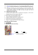
Chapter 4 DRIVER & FREE PROGRAM INSTALLATION Check your package and find the included MAGIC INSTALL CD. This CD consists of all drivers you need and some free bundled application and utility programs. Also included is an auto detection software which can tell you what hardware is installed and which driver is needed for proper system operation. MAGIC INSTALL Supports WINDOWS 98SE/ME/NT4.0/2000/XP Insert CD into your CD-ROM drive and the MAGIC INSTALL Menu should appear as shown below.
4-1 nFORCE Install NVIDIA nFORCE Pack Driver * The path of the file is X:\DRIVER\SETUP.
4-2 Sound Install AC97 Audio Codec Driver 1. Click SOUND when MAGIC INSTALL MENU appears 2. It will auto detect operation system language edition. Click OK to start DRIVER installation 3. Click Finish and Restart Windows 4. Click Start→Program→Avance Sound Manager→AvRack. Then AVRACK Windows appears 5. Sound Effect select and KaraOK Mode Function 6. Manual Sound Effect Setting Note: The path of the file For WIN98/NT4.0/WIN2K/XP is X:\CODEC\ALC\SETUP.
4-3 USB2.0 Install NVIDIA USB 2.0 Driver Windows 98SE/ME/2000 USB 2.0 Driver Installation 1. Click USB2.0 when MAGIC INSTALL MENU appears 2. Click CLOSE and Restart Computer Windows XP USB 2.0 Driver installation 1. Install Windows XP Service Pack 1 or later 2. Select My Computer, Press Right Button, Select Properties, Go to Hardware \ Device Manager, Remove Other Device \ Universal Serial Bus (USB) Controller Restart Your Computer, It Will Find “NVIDIA USB2.0 Enhanced Host Controller” And “USB2.
3. This is license agreement. Select "I Accept 4. Click NEXT and Enter your Customer the terms" and Click NEXT Information. Click NEXT or choose Change to change the path for storing the file 5. Click INSTALL installation to begin software 6. Setup Complete and click FINISH 7. After completing PC-CILLIN 2002 8.
4-5 PC-HEALTH Install NFORCE2 Hardware Doctor Utility The path of the file is X:\83627HD\SETUP.EXE (support WINDOWS 98SE/ME/2000/XP) 1. Click PC-Health when Magic Install Menu 2. Click Next when Winbond Hardware Doctor appears Setup Window appears 3. Click Next to continue installation 4. Select Program Group name or enter a new group name. Click Next and click Finish after setup complete 4-5-1 How To Utilize PC-HEALTH 1. Click Program → Winbond Hardware 2.
3. This is a CPU/System Fan Speed and Temperature status information 4-6 MAGIC BIOS Install BIOS Live Update Utility 1. Click Magic BIOS when Magic Install MENU appears 2. Click Next to install the Magic BIOS in Destination Folder 3. After finish Setup you will have a Magic 4. The above picture will appear after double BIOS icon in your screen click the Magic BIOS icon. You can upgrade BIOS On-line by choose internet.
5. When updating BIOS on-line, the program 6. Click Next if you need to update BIOS. After BIOS is updated, the system will clear CMOS will auto-check your BIOS version and automatically restart 7. Click Yes if you want to update the BIOS, 8. When System programming BIOS don’t turn otherwise choose No to exit off power after finish update BIOS, the system will clear CMOS and automatically Restart 9.
4-7 HOW TO UPDATE BIOS Before update BIOS please choose Disabled in “Flash Part Write Protect” item on “Miscellaneous Control” in BIOS Setup. Please refer to page 32 for detail. Method 1. Method 2. Use “Magic BIOS” to update BIOS in Windows 98 (refer to page 40) In DOS Mode: STEP 1. Prepare a boot diskette. (you may make one by clicking START, clicking RUN, typing SYS A:, and clicking OK) STEP 2. Copy utility program to your boot diskette. You may copy from DRIVER CD X:\FLASH\AWDFLASH.