KM780V Rev: 1.0 USER'S MANUAL Of AMD 780V + SB700 Chipset M/B for Socket AM2+ 64-bit Dual Core AMD Processors Trademark: * Specifications and information contained in this documentation are furnished for information use only, and are subject to change at any time without notice, and should not be construed as a commitment by manufacturer.
Environmental Safety Instruction z Avoid the dusty, humidity and temperature extremes. Do not place the product in any area where it may become wet. z 0 to 40 centigrade is the suitable temperature. (The figure comes from the request of the main chipset) z Generally speaking, dramatic changes in temperature may lead to contact malfunction and crackles due to constant thermal expansion and contraction from the welding spots’ that connect components and PCB.
TABLE OF CONTENT CHAPTER 1 1-1 1-2 1-3 1-4 INTRODUCTION OF AMD 780V MOTHERBOARD SERIES FEATURES OF MOTHERBOARD .................................................................................... 1 1-1.1 SPECIAL FEATURES OF MOTHERBOARD.................................................... 2 ITEM CHECKLIST .............................................................................................................. 2 SPECIFICATION..............................................................................
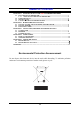
Chapter 1 Introduction of AMD 780V Motherboard Series 1-1 Features of motherboard The AMD 780V Series motherboards are based on the latest AMD780V Chipset and SB700 chipset which supports the new generation innovative 64-bit AMD Socket AM2+ dual core multi-tasking Socket AM2+ Athlon64 X2 processors and dual core AMD Phenom™ processors.
that the over-clocking maybe cause the fails in system reliabilities. This motherboard provides the guaranteed performance and meets the demands of the next generation computing. But if you insist to gain more system performance with variety possibilities of the components you choose, please be careful and make sure to read the detailed descriptions of these value added product features, please get them in the coming section. 1-1.
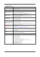
1-3 Specification Spec Description Design ∗ ∗ Chipset ∗ ∗ CPU Socket AM2+ Memory Socket Expansion Slot ∗ ∗ ∗ ∗ ∗ ∗ ∗ Integrate IDE and Serial ATA2 RAID ∗ ∗ Integrated VGA ∗ Micro ATX form factor 4 layers PCB size: 24.5x20.0cm AMD780V Chipset and AMD SB700 Chipset Support 64bit AMD AM2+ 940-Pin package utilizes Flip-Chip Pin Grid Array package compatible processor Support for HTT 1GHz dual core AMD Phenom processors Support HT 3.
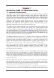
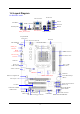
1-4 Layout Diagram For KM780V model RJ-45 LAN VGA Connector Line-IN PS/2 Mouse HDMI Connector Line-OUT PS/2 Keyboard MIC-IN Coaxial SPDIF_Out Connector DVI Connector USB Connector Keyboard/USB Power (JP1) CPU FAN ATX 12V Power Connector PS2 KB/Mouse Port CPU Socket AM2+ SPDIF_Out Connector HDMI Connector DDR2 Socket x2 VGA over DVI Connector ATX Power Conn. USB Port RJ-45 Over USB Connector Audio Connector ATA 133 IDE Conn.
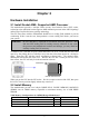
Chapter 2 Hardware Installation 2-1 Install Socket AM2+ Supported AMD Processor This motherboard provides a 940-pin surface mount, Zero Insertion Force (ZIF) socket, referred to as the mPGA940 socket supports AMD Athlon64 processor in the 940 Pin package utilizes Flip-Chip Pin Grid Array package technology. The CPU that comes with the motherboard should have a cooling FAN attached to prevent overheating. If this is not the case, then purchase a correct cooling FAN before you turn on your system.
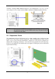
Generally, installing DDRII SDRAM modules to your motherboard is very easy, you can refer to figure 2-4 to see what a 240-Pin DDR2 1066/800/667 SDRAM module looks like.
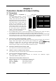
Chapter 3 Connectors, Headers & Jumpers Setting 3-1 Connectors (1) Power Connector (24-pinblock) : ROW1 ROW2 ATXPWR1 PIN ROW1 ROW2 ROW1 ROW2 ATX Power Supply connector: This is a 1 3.3V 3.3V 2 3.3V -12V new defined 24-pins connector that 3 GND GND usually comes with ATX case.
VGA Connector SPDIF_OUT PS/2 Mouse RJ-45 LAN Line-IN Connector Line-OUT PS/2 Keyboard MIC-IN HDMI Connector USB USB DVI Connector (7) Floppy drive Connector (34-pin block): FDD This connector supports the provided floppy drive ribbon cable. After connecting the single plug end to motherboard, connect the two plugs at other end to the floppy drives.
(9) Serial-ATAII Port connector: SATA1~SATA6 These connectors support the provided Serial ATA and Serial ATA2 IDE hard disk cable to connecting the motherboard and serial ATA hard disk. SATA6 SATA5 SATA4 SATA3 SATA2 SATA1 Serial-ATA1 & 2 Compatible Connectors (10) D-Sub 15-pin Connector: VGA VGA is the 15-pin D-Subminiature female connector; it is for the display devices, such as the CRT monitor, LCD monitor and so on.
VCC -DATA +DATA GND OC VCC -DATA +DATA GND USB2 -DATA +DATA GND OC USB1 VCC (2) USB Port Headers (9-pin) : USB1 / USB2 These headers are used for connecting the additional USB port plug. By attaching an option USB cable, your can be provided with two additional USB plugs affixed to the back panel. Pin 1 VCC -DATA +DATA GND Pin 1 USB Port Headers (3) Speaker connector: SPEAK1 This 4-pin connector connects to the case-mounted speaker. See the figure below.
CPUFAN IN CPUFAN OUT GND +12V (8) FAN Power Headers: SYSFAN1, SYSFAN2 (3-pin), CPUFAN (4-pin) These connectors support cooling fans of 350mA (4.2 Watts) or less, depending on the fan manufacturer, the wire and plug may be different. The red wire should be positive, while the black should be ground. Connect the fan’s plug to the board taking into consideration the polarity of connector.
(11) HDMI_SPDIF_Out header: SPDIF_Out The SPDIF output is capable of providing digital audio to external speakers or compressed AC3 data to an external Dolby digital decoder. Use this feature only when your stereo system has digital input function. Some of the VGA Card need connect SPDIF_IN Connector, so its HDMI Port can make sounds.
Note: When should clear CMOS 1. Troubleshooting 2. Forget password 3.
Chapter 4 Useful Help 4-1 How to Update BIOS STEP 1. Prepare a bootable floppy disk. (You may make one by click START click RUN type SYS A: click OK) STEP 2. Download upgrade tools and the latest BIOS files of the motherboard from official website and then make a copy of it to your bootable floppy disk after decompressing these files STEP 3. Insert the disk into A: ,start your computer and then type in “A:\xxxxxx.BAT”(xxxxxxx being the file name of the latest BIOS ) STEP 4.
Chapter 5 Software Setup 5-1 SOFTWARE LIST Category Platform Chipset Driver Windows XP, Vista, XP64, Vista64 Realtek® Lan Driver Windows XP, Vista, XP64, Vista64 ® Realtek Audio Driver Windows XP, Vista, XP64, Vista64 HDMI Audio Driver Windows XP, Vista, XP64, Vista64 5-2 SOFTWARE INSTALLATION Place the Driver CD into the CD-ROM drive and the Installation Utility will auto-run. You can also launch the Driver CD Installation Utility manually by executing the program located on the Driver CD.
Windows XP 64 Windows Vista 64 ◎The screen and images are only for general reference. The version of the screens you received with your software may vary slightly. Click on the "User Manual" button, you can choose the manual to read. If you click the "Browse CD" button, you can browse all the files in the Driver CD. Attention Before you read manuals, you must install the driver of Adobe Acrobat Reader 6 to browse PDF files.
Subject 1: Supply Mold APPENDIX I Regarding the Application of 3-Phase or 3+1 Phase Power As a result of the increasing power consumption demand from many AMD CPUs in current market, we suggest not to use a CPU that demands more than 65W power consumption at work for an AMD CPU compliant board that comes with power supply design as 3 phase or 3+1 phase mold and MOSFET design as working in High SideX1 and Low SideX1 mold so as to avoid MOSFET getting burned or other phenomena like a halted system or system
for CPUs that demand 125W or 140W power consumption. Subject 2: Suggestion on choosing electric fan Both the amount of electric current to MOSFET and the heat produced from the motherboard go up as AMD’s CPU power consumption increases. In this case we recommend users select a CPU fan with air outlet towards MOSFET so that CPU fan can carry away heat produced by MOSFET, for better heat dissipation effects.