
User manual


High-Speed Input and
Pulse Output Features
3--17
High-Speed Input and Pulse Output Features
DL105 PLC User Manual, 3 rd Edition
Mode 20: Quadrature Counter
The counter in the HSIO circuit can count two quadrature signal pulses instead of a
single pulse train (mode 10 operation). Quadrature signals are commonly generated
from incremental encoders, which may be rotary or linear. The quadrature counter
has a range from 0 to 99999999, and can count at up to a 5 kHz rate, using CT76 and
CT77. Unlike Mode 10 operation, the quadrature counter can count UP or DOWN,
but does not feature automated preset values or “interrupt on external reset”
capability. However, you have the standard ladder instruction preset of CT76.
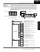
The diagram below shows HSIO functionality in Mode 20. When the lower byte of
HSIO Mode register V7633 contains a BCD “20”, the quadrature counter in the HSIO
circuit is enabled. Input X0 is dedicated to the Phase A quadrature signal, and input
X1 receives Phase B signal. X2 is dedicated to reset the counter to zero value when
energized. X3 can only be a regular filtered input in Mode 20.
Output Circuit
Input Circuit
CPU
PLC
DL105
X0
Y0, Y1
X4 -- X11
Y2 -- Y7
V-memory
V7633
xx20
Mode Select
I/O data
HSIO
COUNTER
Phase
A
Phase
B
X2 X3
Reset
X1
FILTER
Quadrature encoder signals contain position and direction information, while their
frequency represents speed of motion. Phase A and B signals shown below are
phase-shifted 90 degrees, thus the quadrature name. When the rising edge of
Phase A precedes Phase B’s leading edge (indicates clockwise motion by
convention), the HSIO counter counts UP. If Phase B’s rising edge precedes Phase
A’s rising edge (indicates counter-clockwise motion), the counter counts DOWN.
90° phase shift
Phase A
Phase B
Leading Edge Signal
Phase A
Phase B
Leading Edge Signal
Clockwise sequence
Counterclockwise sequence
one cycle
Purpose
Functional Block
Diagram
Quadrature
Encoder Signals