53 Cordaville Rd • Suite 310 • Southboro, MA 01772 • Phone: 508-983-0983 • Fax: 508-983-0984 XpressROMTM User’s Guide Revision History Revision 1.0 1.2 1.4 1.6 1.8 1.9 2.
Table of Contents Overview......................................................................................................................................... 3 Quick Start ...................................................................................................................................... 3 Setup Menu Screens and Navigation .............................................................................................. 4 Main Menu ........................................................
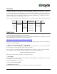
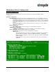
Overview The following document is a user’s guide for Insyde’s XpressROMTM firmware for the AMD GeodeTM processors including the AMD GeodeTM NX, LX, GX, SC1200, SC2200, SC3200, and GX1 processors. The user’s guide will show you the menu systems for the firmware and a mechanism for flashing the BIOS on your platform. Insyde has been working with AMD on the XpressROMTM firmware since 1999 and maintains a development relationship with AMD.
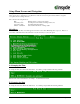
Setup Menu Screens and Navigation The XpressROMTM Setup Menu contains a number of features and options. It is recommend that you evaluate the menu options prior to shipment of your platform to ensure the removal of options that could have a negative consequence if users change the items.
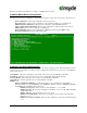
Enter the date in the format listed as an example: 12/16/2005 then hit C. Mother Board Device Configuration The Mother Board Device configuration contains the only sub menu system of the setup screens. The choices are Drive Configuration: Allows the configuration of the storage devices. LPC Card devices: Allows for the configuration of the serial and parallel ports on an LPC Card. DDMA Channel Configuration: Allows for the configuration of the ISA DMA channels.
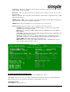
CAS Latency: Allows the configuration Column Address Select latency. The options are Auto, 1.5CLK, 2CLK, 2.5CLK, 3CLK, and 3.5CLK Refresh rate: Allows the setting of the memory refresh rate. Options include: Auto, 15us, 3us, 7us, 31us, 62us and 125us Interleave selection: Allows the setting of the interleaving to either LOI (Low Order Interleaving) or HOI (High Order Interleaving) XOR BA0, BA1, or MB0: Allows the enable or disable of the XORing of module bank BA1or BA0 with upper GLIU address bit.
GeodeLink Multiplier: Options from 1 to 33 The formulae for the CPU Multiplier and GeodeLink Multiplier are as follows 33.3 Mhz * CPU Multiplier = CPU speed 33.3 Mhz *GeodeLink Multiplier = GeodeLinkTM speed. F. Power Management The Power Management menu is for configuration of the BIOS’s power management with relation to the OS on the platform.
H. Miscellaneous Configuration The Miscellaneous configuration screen focuses on a variety of functions, Use the ( ) to select the function and to change the value Splash Screen Configuration Splash Screen: Allows the configuration to have the splash screen displayed or not. The options are Enabled or Disabled. Clear Splash Screen: Allows the system to leave the splash screen on until the operating systems clears the screen. The options are Enabled or Disabled.
Memory Mapped to ISA Mem Range-0 though Mem Range-3: Allows the memory range to be Enabled or Disabled. Size: Selects the memory range size. It may be set to 16K, 32K, 64K, 128K, 256K, 512K, 1M, or 2M Bytes. Base Addr (A23-A16) / (A15-A8): Sets the base address for the memory range. O. Boot Order The Boot Order menu allows the alteration of the devices checked for a bootable image. There are six slots for selecting the order.
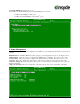
Motherboard Device Configuration C-A Drive Configuration The drive configuration screen determines the setup for the Hard drives, Floppy, CD-ROM, and Flash configurations. Hard Drive Configuration IDE BIOS Support: Allows the configuration of the IDE channel. The options are Enabled or Disabled. 80-Conductor Cable Sense: Selects the GPIO that is connected to the IDE –PDIAG sense. The options are None (Disabled), Force 40 Conductor Cable, Force 80 Conductor Cable, and GPIO 05.
C-C LPC Card devices The LPC card configuration enables the configuration of each serial port and the parallel port on the LPC. To change the serial port configuration use the arrow keys ( ) to select the serial port and hit to change the state. The choices are Disabled, 0x3F8 IRQ 4, 0x2F8 IRQ 3, 0x3E8 IRQ 4, 0x2E8 IRQ3 Serial Port 1-2: Allows the selection of the serial port address and IRQ. The choices are Disabled, 0x3f8 IRQ 4, 0x2f8 IRQ 3, 0x3e8 IRQ 4, and 0x2e8 IRQ 3.
C-F. Video and Flat Panel Configuration The following menu allows you to configure graphics settings for the system. To change an option, select the field using the arrow keys and then select to change the value of the field. The menu system will also display the bond out option for the parts, either flat panel or CRT. Internal Adapter Mode: Allows you to select the mode for the internal controller when an external video device is present.
HSYNC Polarity: Selects the active polarity of the HSYNC signal to the panel. The options are Active Low or Active High. VSYNC Polarity: Selects the active polarity of the VSYNC signal to the panel. The options are Active Low or Active High. LP Active Period: Selects the active period of the LDE/MOD (LP) signal. The options are Free Running and Active Only. SHFCLK Active Period: Selects the active period of the SHFCHK signal.
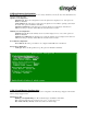
C-P PCI Configuration The following menu system allows the configuration of the PCI interrupts and SMBus setting. PCI Interrupt Steering PCI INT A# - INT D#: Use to cycle through the selections. The selections are Disabled, IRQ 1, IRQ 3, IRQ 4, IRQ 5, IRQ 6, IRQ 7, IRQ 9, IRQ 10, IRQ 11, IRQ 12, IRQ 14, and IRQ 15. SMBus Setting SMBus: The PCI header of the SMBus may be Enabled or Disabled.
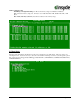
C-T Thermal Configuration The Thermal Configuration screen reads the current state of the CPU temperature from the LM82. The value is in Celsius. Conclusion If there are any issues or questions on this product please contact: Americas, Europe and Africa Brian Gosselin bgosselin@insydetech.com 508-983-0983 x139 Asia Pacific Daniel Lin Daniel.lin@insydesw.com.tw 886-2-2506-1289 x511 Insyde Technology, Inc. 153 Cordaville Rd.