
Specifications


240 AMD Geode™ GeodeROM Functional Specification
Power Management
32087C
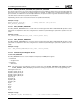
17.2 PM Initialization
Initialization requirements of power management consist primarily of writing various virtual registers within the PM virtual
register class (see Table 17-1 on page 240). The sample code that follows demonstrates how to write a single virtual regis-
ter:
MOV DX, 0AC1Ch ; virtual register index
MOV AH, 04h ; PM class
MOV AL, 02h ; Doze timeout register
OUT DX, AX
ADD DX, 2 ; virtual register data
MOV AX, <doze_timeout> ; units = seconds
OUT DX, AX
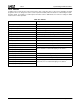
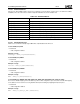
Table 17-1. PM Virtual Registers
Register Defined As Description
0401h PM_MODE Defines the PM API (e.g. APM, Legacy, etc.) currently in use. This register
is written by a PM VSM. It is not initialized by the boot ROM.
01h POWER_STATE Defines the desired power state. This register is written by a PM VSM. It is
not initialized by the boot ROM.
02h
DOZE_TIMEOUT
1
Defines the duration of system idleness (in seconds), defined as lack of
user input, after which the system is transitioned to the DOZE power state.
03h
STANDBY_TIMEOUT
1
Defines the duration of system idleness (in seconds), as lack of user input,
after which the system is transitioned to the STANDBY power state.
04h
SUSPEND_TIMEOUT
1
Defines the duration of system idleness (in seconds), as lack of user input,
after which the system is transitioned to the SUSPEND power state.
05h KEYBOARD_TIMEOUT Defines duration inactivity of the keyboard before the system is considered
idle.
06h MOUSE_TIMEOUT Defines duration inactivity of the mouse before the system is considered
idle.
07h VIDEO_TIMEOUT Defines duration inactivity of the video before the system is considered
idle.
08h
DISK_TIMEOUT
1
Defines duration of the hard drive idleness (in seconds), as lack of I/O to
the IDE interface, after which the disk drive(s) are spun down.
09h
FLOPPY_TIMEOUT
1
Defines duration of the floppy drive idleness (in seconds), as lack of floppy
I/O, after which the floppy subsystem is put in a low power state. This type
of power control is typically located in the superI/O chipset.
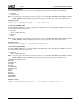
0Ah
SERIAL_TIMEOUT
1
Defines the duration of serial port idleness (in seconds), as lack of COM I/
O, after which the serial port subsystem is put in a low power state. This
type of power control is typically located in the superI/O chipset.
0Bh
PARALLEL_TIMEOUT
1
Defines the duration of parallel port idleness (in seconds), as lack of LPT
I/O, after which the parallel port subsystem is put in a low power state.
This type of power control is typically located in the superI/O chipset.
0Ch IRQ_WAKEUP_MASK A mask of IRQs (LSB = IRQ0; MSB = IRQ15) that are to be used as wake-
up events from STANDBY mode. These typically include IRQ1 (keyboard),
IRQ12 (PS/2 mouse), as well as others such as IRQ3/4 (modem) or net-
work IRQs.
0Dh SUSPEND_MODULATION Defines the effective clock frequency to be used during DOZE mode. The
upper byte defines the OFF time while the lower byte defines the ON time.
For example, 0x0901 would yield a 10% effective clock speed.
0Eh VIDEO_SPEEDUP Defines the number of milliseconds that video activity disables clock throt-
tling (DOZE power state). After the time lapse, clock throttling resumes.
0Fh IRQ_SPEEDUP Defines the number of milliseconds that IRQ activity disables clock throt-
tling (DOZE power state). After the time lapse, clock throttling resumes.
10h WAKEUP_SMI_MASK Not implemented: Reserved.