
Specifications


AMD Geode™ GeodeROM Functional Specification 219
System Management Mode Software
32087C
15.9 Virtual Registers
Virtual registers (VR) are I/O locations accessed with 16-bit index/data operations. The Geode hardware can be configured
to trap I/O accesses. VSA2 interprets the data values and either treats the data as parameters (e.g., PM time-outs) or per-
forms some function (e.g., change the TV encoder brightness).
VRs provide a uniform method for the BIOS or third-party software to customize VSA2 software parameters and features
(e.g., PM time-outs). They are also the mechanism by which one VSM communicates with another.
WARNING: The effects of accessing the VR should appear to occur immediately to the VSM. Accessing a VR from within a
VSA critical section produces unpredictable results.
VRs may be used to read or write information to or from VSA2 software. The registers consist of an index/data pair of I/O
locations (AC1Ch, AC1Eh). The System Manager is responsible for setting up the I/O trapping to support VRs. A VSM
should use the SET_VIRTUAL_REGISTER and GET_VIRTUAL_REGISTER macros rather than directly executing the I/O
cycle.
An unlock cycle is required prior to accessing a VR and must be executed upon every access. This feature protects the I/O
space from undesirable probing by various operating systems.
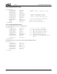
Index Value:
Data Value:
The index is a WORD, consisting of a VR class and parameter ID. The data is also a WORD. Below is sample code for writ-
ing the Standby timeout.
MOV AX, 0FC53h ; unlock code
MOV DX, 0AC1Ch
OUT DX, AX ;
MOV AH, 4 ; power management class
MOV AL, 3 ; standby timeout
OUT DX, AX
ADD DX, 2 ; point to data register
MOV AX, 60 ; set to 1 minute
OUT DX, AX
Parameter Description
AH Class
AL Parameter_ID
Parameter Description
AX Data