7ZMMC TM AMD Athlon /Duron TM Socket A Processor Motherboard USER'S MANUAL AMD AthlonTM/DuronTM Socket A Processor Motherboard REV. 2.
FCC Compliance Statement: DECLARATION OF CONFORMITY Per FCC Part 2 Section 2. 1077(a) Responsible Party Name: G.B.T. INC. Address: 18305 Valley Blvd., Suite#A LA Puent, CA 91744 Phone/Fax No: (818) 854-9338/ (818) 854-9339 hereby declares that the product Product Name: Mother Board Model Number: GA-7ZMMC Conforms to the following specifications: FCC Part 15, Subpart B, Section 15.107(a) and Section 15.
Declaration of Conformity We, Manufacturer/Importer (full address) G.B.T.
7ZMMC Motherboard Table Of Content FEATURE SUMMARY ........................................................................................................................................ 1 7ZMMC MOTHERBOARD LAYOUT............................................................................................................... 2 CPU SPEED SETUP ............................................................................................................................................. 3 SW1: CPU SPEED SETUP ..
7ZMMC Motherboard Feature Summary Form Factor CPU Chipset Clock Generator Memory I/O Control Slots On-Board IDE On-Board Peripherals Hardware Monitor PS/2 Connector On-Board VGA On-Board Sound BIOS Additional Features 24.4 cm x 22.2 cm Micro ATX size form factor, 4 layers PCB.
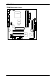
7ZMMC Motherboard 7ZMMC Motherboard Layout JP4 J3 USB1 PS/2 LPT COM A ATX POWER Socket A CPU JP6 FLOPPY VGA JP8 LED1 JP7 IDE1 IDE2 DIMM2 7ZMMC Creative CT5880 DIMM1 J9 J7 GAME & AUDIO VT8365 SW1 BAT1 PCI1 JP3 J8 J13 PCI2 VT82C 686B J16 BIOS J2 PCI3 J17 CNR J12 J18 J11 USB2 2 JP9 CODEC AGP 1
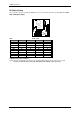
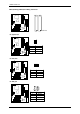
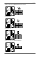
ZMMC Motherboard CPU Speed Setup The system bus speed is selectable at 100MHz. The user can select the system bus speed by DIP switch SW1. SW1: CPU Speed Setup SW1: FSB 95 100 102 103 107 110 113 115 133 O: ON, X: OFF 1 O X 0 X O 0 X X X 2 O O 0 O X X X X X 3 X X X X O 0 O X X 4 O X X O 0 X O 0 X AMD CPU Heat Sink Installation: Beware: Please check that the heat sink is in good contact with the CPU before you turn on your system.
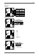
Connectors Connectors ATX Power 10 20 1 11 Pin No. Definition 3,5,7,13, GND 15-17 1,2,11 3.
7ZMMC Motherboard IDE1 (Primary), IDE2 (Secondary) Connector IDE 2 IDE 1 Red Line J2: Sysem Fan 1 Pin No. Definition 1 Control 2 +12V 3 SENSE J3: CPU Fan 1 Pin No. Definition 1 Control 2 +12V 3 SENSE J7: AUX_IN 1 Pin No.
Connectors J8 TEL: The connector is for Modem with internal voice connector 1 Pin No. Definition 1 Signal-In 2 GND 3 GND 4 Signal-Out J9: CD Audio Line In 1 Pin No. 1 2 3 4 Definition CD-L GND GND CD-R J12: Wake On LAN 1 Pin No. Definition 1 +5V SB 2 GND 3 Signal J13: Ring Power On (Internal Modem Card Wake Up) 1 Pin No.
7ZMMC Motherboard JP6: Power Fan 1 Pin No. Definition 1 Control 2 +12V 3 NC JP8 / LED1: STR LED Connector & DIMM LED STR LED Connector External. 1 + DIMM LED PS/2 Keyboard & PS/2 Mouse Port PS/2 Mouse/Keyboard Pin No. Definition 5 6 1 Data 2 NC 3 4 3 GND 1 2 4 VCC(+5V) PS/2 Keyboard 5 Clock 6 NC PS/2 Mouse USB 1: Rear USB Port 5 6 7 8 1 23 4 Pin No.
Connectors USB 2: Front USB Connector 2 10 1 9 Pin No.
7ZMMC Motherboard Panel And Jumper Definition BAT1: Battery + CAUTION ☞ Danger of explosion if battery is incorrectly replaced. ☞ Replace only with the same or equivalent type recommended by the manufacturer. ☞ Dispose of used batteries according to the manufacturer’s instructions.
Panel and Jumper Definition J16 /J17/J18: CNR (Primary or Secondary) Select [Optional] (CNR Communication and Networking Riser) 1 J16 J17 1 J18 1 Onboard AC97 CNR (Primary) Onboard AC97 CNR (Secondary) [Optional] J16 1-2 2-3 1-2 J17 1-2 3-4 1-2 3-4 J18 1-2 3-4 1-2 JP3: Clear CMOS Function (Optional) 1 Pin No. Definition 1-2 close Normal (Default) 2-3 close Clear CMOS JP4: USB Device Wake up Selection 1 Pin No.
7ZMMC Motherboard JP7: STR Function Enable 1 Pin No. Definition 1-2 close STR Enable 2-3 close Normal (Default) JP9: BIOS Write Protect Function 1 Pin No. Definition 1-2 close Write Protect Enable 2-3 close Write Protect Disable (Default) Please set Jumper JP9 to “2-3 close” to enabled BIOS write function when you update new BIOS or new device.
7ZMMC Motherboard Memory Installation The motherboard has 2 dual inline memory module (DIMM) sockets. The BIOS will automatically detects memory type and size. To install the memory module, just push it vertically into the DIMM Slot .The DIMM module can only fit in one direction due to the two notch. Memory size can vary between sockets.
7ZMMC Motherboard BIOS Setup BIOS Setup is an overview of the BIOS Setup Program. The program that allows users to modify the basic system configuration. This type of information is stored in battery-backed CMOS RAM so that it retains the Setup information when the power is turned off. ENTERING SETUP Power ON the computer and press immediately will allow you to enter Setup.
BIOS Setup The Main Menu Once you enter AMI BIOS CMOS Setup Utility, the Main Menu (Figure 1) will appear on the screen. The Main Menu allows you to select from nine setup functions and two exit choices. Use arrow keys to select among the items and press to accept or enter the sub-menu. AMIBIOS SIMPLE SETUP UTILITY-VERSION 1.24a ( C ) 1999 American Megatrends, Inc.
7ZMMC Motherboard • User password Change, set, or disable password. It allows you to limit access to the system. • IDE HDD auto detection Automatically configure hard disk parameters. • Save & Exit Setup Save CMOS value settings to CMOS and exit setup. • Exit Without Saving Abandon all CMOS value changes and exit setup. Standard CMOS Setup The items in Standard CMOS Features Menu (Figure 2) are divided into 9 categories. Each category includes no, one or more than one setup items.
BIOS Setup If you select User Type, related information will be asked to enter to the following items. Enter the information directly from the keyboard and press . Such information should be provided in the documentation form your hard disk vendor or the system manufacturer. CYLS. Number of cylinders HEADS number of heads PRECOMP write precomp LANDZONE Landing zone SECTORS number of sectors If a hard disk has not been installed select NONE and press .
7ZMMC Motherboard BIOS Features Setup AMIBIOS SETUP – BIOS FEATURES SETUP ( C ) 1999 American Megatrends, Inc. All Rights Reserved 1st Boot Device Floppy 2nd Boot Device CDROM 3rd Boot Device IDE-0 S.M.A.R.T.
BIOS Setup Chipset Features Setup AMIBIOS SETUP – CHIPSET FEATURES SETUP ( C ) 1999 American Megatrends, Inc. All Rights Reserved Configure Timing by SPD Enabled DRAM Frequency Auto SDRAM CAS# Latency Auto AGP Mode AGP Comp. Driving Manual AGP Comp.
7ZMMC Motherboard • AGP Aperture Size 4MB 8MB 16MB 32MB 64MB 128MB 256MB Set AGP Aperture Size to 4MB. Set AGP Aperture Size to 8 MB. Set AGP Aperture Size to 16 MB. Set AGP Aperture Size to 32 MB. Set AGP Aperture Size to 64 MB. (Default Value) Set AGP Aperture Size to 128 MB. Set AGP Aperture Size to 256 MB. • ClkGen Spread Spectrum Disabled Enabled Disable ClkGen Spread Spectrum. Enable ClkGen Spread Spectrum.
BIOS Setup Power Management Setup AMIBIOS SETUP – POWER MANAGEMENT SETUP ( C ) 1999 American Megatrends, Inc.
7ZMMC Motherboard • System after AC Back Last State Off On System power on depends on the status before AC lost. (Default Value) Always in Off state when AC back. Always power on the system when AC back. • Resume On Ring / LAN Disabled Enabled Disable Resume On Ring / LAN. Enable Resume On Ring / LAN. (Default Value) • Resume On PME# Disabled Enabled Disable Resume On PME#. Enable Resume On PME#.
BIOS Setup PNP/PCI Configurations AMIBIOS SETUP – PNP / PCI CONFIGURATION ( C ) 1999 American Megatrends, Inc.
7ZMMC Motherboard Load BIOS Defaults AMIBIOS SIMPLE SETUP UTILITY-VERSION 1.24a ( C ) 1999 American Megatrends, Inc.
BIOS Setup Load Setup Defaults AMIBIOS SIMPLE SETUP UTILITY-VERSION 1.24a ( C ) 1999 American Megatrends, Inc.
7ZMMC Motherboard Integrated Peripherals AMIBIOS SETUP – INTEGRATED PERIPHERALS ( C ) 1999 American Megatrends, Inc.
BIOS Setup • Parallel Port IRQ 7 Auto 5 Set Parallel Port IRQ to 7. Set Auto to parallel Port IRQ DMA Channel. (Default Value) Set Parallel Port IRQ to 5. • OnBoard IDE Disabled Both Primary Secondary Disable OnBoard IDE. Set OnBoard IDE to Both. (Default Value) Set OnBoard IDE to Primary. Set OnBoard IDE to Secondary. • OnBoard AC’97 Audio Auto Disabled Auto detect OnBoard AC’97 Audio. (Default Value) Disable OnBoard AC’97 Audio. • OnBoard MC’97 Modem Auto Disabled Auto detect OnBoard MC’97 Modem.
7ZMMC Motherboard Hardware Monitor AMIBIOS SETUP – HARDWARE MONITOR SETUP ( C ) 1999 American Megatrends, Inc. All Rights Reserved CPU Temperature 47°C/116°F System Temperature 32°C/89°F CPU Fan Speed 7123 RPM System Fan Speed 0 RPM Vcore 1.750 V Vdd 3.050 V Vcc3 3.340 V +5.000V 4.996 V +12.000V 12.166 V ESC: Quit ↑↓→ ←: Select Item F1 : Help PU/PD+/-/ : Modify F5 :Old Values (Shift)F2:Color F6 : Load BIOS Defaults F7 : Load Setup Defaults Figure 10: Hardware Monitor • CPU Temperature.
BIOS Setup Set Supervisor / User Password When you select this function, the following message will appear at the center of the screen to assist you in creating a password. AMIBIOS SIMPLE SETUP UTILITY-VERSION 1.24a ( C ) 1999 American Megatrends, Inc.
7ZMMC Motherboard IDE HDD AUTO Detection AMIBIOS SETUP – STANDARD CMOS SETUP ( C ) 1999 American Megatrends, Inc. All Rights Reserved Date (mm/dd/yyyy) : Tue Jan 25, 2000 Time (hh/mm/ss) : 10:36:24 TYPE SIZE CYLS HEAD PRECOMP LANDZ SECTOR MODE Pri Master : Not Installed Pri Slave : Not Installed Sec Master : Not Installed Sec Slave : Not Installed Floppy Drive A: 1.
BIOS Setup Save & Exit Setup AMIBIOS SIMPLE SETUP UTILITY-VERSION 1.24a ( C ) 1999 American Megatrends, Inc.
7ZMMC Motherboard Exit Without Saving AMIBIOS SIMPLE SETUP UTILITY-VERSION 1.24a ( C ) 1999 American Megatrends, Inc.
7ZMMC Motherboard Appendix: Acronyms Acronyms ACPI APM AGP AMR ACR BIOS CPU CMOS CRIMM CNR DMA DMI DIMM DRM DRAM DDR ECP ESCD ECC EMC EPP ESD FDD FSB HDD IDE IRQ I/O IOAPIC ISA LAN LBA LED MHz MIDI MTH MPT NIC OS OEM PAC POST PCI RIMM SCI SECC SRAM SMP SMI USB VID Meaning Advanced Configuration and Power Interface Advanced Power Management Accelerated Graphics Port Audio Modem Riser Advanced Communications Riser Basic Input / Output System Central Processing Unit Complementary Metal Oxide Semiconductor Co