
User`s guide


Chapter 3
35
5.
POWER ON Function:
This control show the PS/2 mouse or keyboard can power on the system. Available
settings are [Password], [Hot KEY], [Mouse Move], [Mouse Click], [Any Key],
[BUTTON ONLY] and [Keyboard 98].
6.
KB Power ON Password:
If POWER ON Function is set to [Password], then you can set a password in the
field for the PS/2 keyboard to power on the system.
7. Hot Key Power ON:
If POWER ON Function is set to [Hot KEY], you can assign a hot key combination
in the field for the PS/2 keyboard to power on the system.
Settings:[Ctrl-F1] through [Ctrl-F12].
3-6 PNP/PCI Configurations
This section provides IRQ and DMA setting information. By choosing the PNP/PCI
Configuration option from the CMOS Setup Utility menu (Figure 3-1), the screen
below is displayed. This screen contains the manufacturer's default values for the
motherboard.
Reset Configuration Data:
If you want to reset CMOS IRQ divide hardware device, please selected to [Enabled].
Resources Controlled By:
When set to Manual the system BIOS will not refer to the ESCD for IRQ & DMA
information. Instead, it will refer to the items in the setup menu for assigning IRQ &
DMA. When set to Auto the system BIOS will refer to the ESCD for all legacy
information. ESCD (
Extended System Configuration Data
) provides a detailed
format of the configuration data structures stored in flash memory. Each data structure
defines the resources used by a device or a card in the system. This includes legacy
and PCI/ISA PnP devices.
PCI/VGA Palette Snoop:
When set to [Enabled], multiple VGA devices operating on different buses can handle
data from the CPU on each set of palette registers on every video device. Bit 5 of the
command register in the PCI device configuration space is the VGA Palette Snoop bit
(0 is disabled). Available options are [
Enabled
] and [
Disabled
].
FDD IRQ Can Be Free:
This function allows user to choose if the FDD IRQ can be freed up. The default
setting is [Yes] and this does not allow the IRQ to be free.
Chapter 3
36
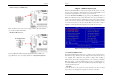
3-7 PC Health Status
By choosing the PC Health Status option from the CMOS Setup Utility menu (Figure
3-1), the screen below is displayed. This field shows you the current CPU
temperature/external voltages input and the current CPU FAN operating speed.
Shutdown Temperature:
This item allows you to set the shutdown temperature level for the processor. When
the processor reaches the temperature you set, the system will shutdown. This
function only works in ACPI-aware OS (such as Windows® 98 / ME / 2000).
Available options are [85°C/185°F], [90°C/194°F], [95°C/203°C] and [100°C/210°F]
3-8 Frequency/Voltage Control
By choosing the Frequency/Voltage Control option from the CMOS Setup Utility
menu (Figure 3-1), the screen below is displayed. This sample screen contains the
manufacturer's default values for the motherboard.
FSB/AGP Spread Spectrum:
This item is used to enable or disable the clock generator’s Spread Spectrum feature.
When over clocking the processor, always set it to Disabled. Setting options: [
0.5%
],
[1.00%], and [Disabled]
OVERCLOCKING
This motherboard is designed to support overclocking. However, please make
sure your components are able to tolerate su
ch abnormal setting, while doing
overclocking. Any attempt to operate beyond product specifications is not
recommended.
We do not guarantee the damages or risks caused by
inadequate operation or beyond product specifications.
3-9 Load Fail-Safe Defaults
Load Fail-Safe Defaults loads the default BIOS values directly from the CMOS Setup
Utility menu (Figure 3-1). If the stored record created by the setup program becomes
corrupted and therefore unusable, these defaults will be loaded automatically when
you turn on the computer.
3-10 Load Optimized Defaults
Load Optimized Defaults loads the default system values directly from the CMOS
Setup Utility menu (Figure 3-1). If the stored record created by the setup program
becomes corrupted and therefore unusable, these defaults will be loaded automatically
when you turn on the computer.