
User Guide
User manual-amc TR1a_G
Page 7 of 17
PN: 21-TR1a_IM
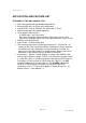
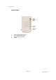
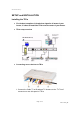
FRONT SIDE PANEL
1. Connector for IR Blaster
The 3.5mm mini connector is for IR
Blaster Output. IR Blasters can be
hooked up to the connector.
2. Connector for Stereo Audio
Pre-Out (Option)
The 3.5mm mini connector is for
Stereo Audio Pre-Out. The Pre-Out
is for connecting to external Stereo
Audio systems and the latency
between the Pre-Out and Video will
have to be adjusted by time delay
module. So, the Pre-Out is an option
and will be installed for special
designed projects and according to
special orders only.
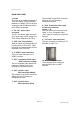
FRONT PANEL
1. LED 1 (Orange) Wireless LED
Blinking slowly : wireless is
connecting
Blinking quickly : wireless is
connected and transmitting data
2. LED 2 (Green) Power LED
This is a Power On LED.
3. LED 3 (Red) Tuner Status
Tuner Initialization Confirmed
4. RESET
This is a switch to reset TR1a.
When TR1a experiences unstable
operation or trouble for connecting,
you can use the switch to reset TR1a
by following procedure,
a. Switch off the TR1a
b. Press and hold the reset button
and then switch on TR1a
c. Wait for 5 seconds and then
release the reset button.
d. the TR1a should have then been
reset to factory default setup.