
Operating instructions
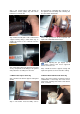
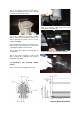
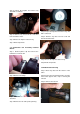
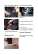
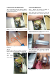

3.3 Burner Removal (All Options)
Step 1 Isolate mains electric and gas
supplies.
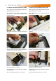
Step 2 Detach the gas supply as shown below,
taking care to support the burner connection.
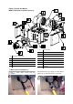
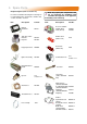
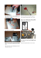
F Ignition Probes
G Gas Valve
H Multi Hole Injector
I Neon's (Red/Amber)
J Ignition Controller
K Extrusion Burner Head
L Pepperpot Head
M Pressure Switch
J Jet Carrier
A 2501/2507 or 2560 Fan
B Fan Inlet Spigot
C Fan Orifice
D Fan Mount Plate
E Fan Mount Plate Gasket
Please refer to spares for burner components
Figure 4. Forced Gas Burner:
Model VSXO (refer to spares section 5)