INSTALLATION INSTRUCTION MANUAL FOR AMBIRAD VISION® VSO & VSXO RANGE OF RADIANT TUBE HEATERS INDEX Section Introduction, Document Index & Tools Required Installation Requirements -------------------------------------------------1 User and Operating Instructions ----------------------------------------2 WARNINGS AmbiRad equipment must be installed and maintained in accordance with the relevant provisions of the Gas Safety (Installations and Use) Regulations 1998 for gas fired products.
Introduction. Welcome to the new range of high efficiency AmbiRad Vision radiant tube heaters. Local regulations may vary in the country of use and it is the installers responsibility to ensure that such regulations are satisfied All installation, assembly, commissioning and service procedures must be carried out by suitable qualified competent persons to the statutory regulations in the country of use.
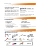
1. Installation Requirements. 1.1 Isolate any electrical supply to the heater and controller before proceeding. additional steelwork should be fitted to enable vertical hangers to be used for suspending the heaters. Health and Safety If there are any doubts as to the strength or suitability of roof steelwork to which heaters are to be suspended, please refer to a Consultant, Architect or owner of the building. The recommended mounting heights for AmbiRad heaters are given in the table below.
* * These angles to be equal and not more than 45°. Vertical suspension chain ideal. Where supports are inclined, maximum recommended angle of inclination is 15°. Typical Speedlink attachment. Shackle method of attachment. Pin must be tightened by pliers. Drop rod with formed hook. note. hook or eyebolt must be closed tight. ON U TUBE VARIANTS THE HEATER SHOULD SLOPE DOWNWARDS TOWARDS THE RETURN BEND BY APPROX. 10mm FOR BOTH HORIZONTAL AND WALL MOUNTED INSTALLATIONS.
1.5 Herringbone Systems (VSOUH). The manifold system should be arranged to fall slightly in the direction of the vacuum fan. This ensures that any condensation formed in the manifold on cold start and cool down is not trapped or allowed to drain back into the heater unit. This allows condensate to flow towards the condensate trap located at the vacuum fan end of the manifold system. (See figure 4a below for condensate trap arrangement).
305.0 For details of fan mounting bracket and fixing down holes see figure 5. Figure 4g. Stainless Steel Telescopic Through The Wall Arrangement (available for Type ‘O’ and Type ‘2’ fans) Figure 4e. Conventional Flue Arrangement Roof Exit. Where a conventional flue is to be installed, AmbiRad supply an aluminium transformation piece to which a 150mm (6ins) diameter flue must be attached. The length of flue which may be connected to the fan outlet must be adequately supported from the building structure.
Figure 5. Vacuum fan mounting details (Type ‘O’ fan illustrated) Hole Centers Fig 4c/d Hole Centers Fan Type O Type 2 A 124 80 B 38 35 C 175 174 D 7.1 7 E 209 125 F 153 100 G 42 25 H 239 120 J 340 210 K 332 205 L 363 215 Power (watts) 550 120 Running Current (amps) 2.6 0.
Figure 6. Typical Herringbone system (VSO shown with optional end covers) Dos and don'ts of herringbone system Dos Don’ts Check design pressure drop. Run drains in copper or mild steel pipework. Check for corrosive industrial process in Install system with extra 90° bends without asking proposed building - e.g. cleaning, electroplating, AmbiRad if the system will operate correctly. printers using sugar powder etc. Drain all flue ducts and seal all joints.
1.6 Clearance to Combustibles. The minimum clearances to combustible materials are given in the tables below. These minimum distances MUST be adhered to at all times. Figure 7.
Figure 7.
Figure 7.
1.7 Gas Connection and Supply to the heater not to apply excessive turning force to the internal controls. Before installation, check that the local distribution conditions, nature of gas and pressure, and adjustment of the appliance are compatible. A competent or qualified engineer is required to either install a new gas meter to the service pipe or to check that the existing meter is adequate to deal with the rate of gas supply required.
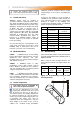
Care must be taken to observe the minimum pipe bend diameter (minimum 250mm, maximum 350mm) & pipe expansion distance (minimum 30mm, maximum 70mm) as shown in fig.e. Depending on the specific installation, the flexible gas hose may be routed to the gas cock at any of the following angles in relation to the burner: Vertical 45° angle 90° angle (fig.a) (fig.b) (fig.c) Maximum bend diameter for the 1000mm hose is 450mm.
Figure 9.b Typical VSOUT Induced Unitary Wiring Connections (end covers not shown) Fused Spur Fan plugs into burner Figure 9.c Typical VSOUH Herringbone Wiring Connections (end covers not shown) Fused Spur Figure 9.d Typical VSXO Powered Burner Unitary Wiring Connections (end covers not shown) Fused Spur Fan plugs into burner Figure 9.e Typical VSXO Powered burner Wiring Connections (end covers shown) Fused Spur Fan plugs into burner Figure 10. Internal Burner Wiring Diagram.
Figure 10. Internal Burner Wiring Diagram. FAN L GREY VACUUM SWITCH N SOLENOID VALVE N.C. C. N.O. GREEN/YELLOW VALVE J.S.T. 2 1 3 BLUE EMC FILTER GRN/YLW MAINS INPUT N L BLUE BLUE BLUE MAINS ON GRN/YEL BROWN BROWN 1 2 WHITE MAIN J.S.T.
Figure 11. Typical VSO UH Schematic Wiring Connections 1 phase 230V Exhaust Fan Isolator Tail Pipe Isolator Isolator 0.75mm² Screened Cable Isolator Sensor Zone A Isolator 230V 50Hz 13A Controller Mains Supply 1.9 Ventilation Requirements AmbiRad tube heaters can be operated as flued or unflued appliances in accordance with the relevant national requirements in the country of installation.
Option 1 - Figure 12a. Air Inlet Attachments Unitary Herringbone Burners (VSO) For non-flued installations, delete items A and B and rotate fan outlet to the HORIZONTAL position away from the burner. Ducted Air Intake Products of Combustion D A E B C Firing tube Products of combustion Ventilation requirements are as detailed in section 1.9 Ducted air must be used in locations where there is airborne dust or where there is a polluted atmosphere e.g. Chlorinated Vapours.
Option 1 - Figure 12b. Air Inlet Attachments Induced Herringbone Burners (VSO) Ducted Air Intake C B A D Firing tube Products of Combustion Ventilation requirements are as detailed in section 1.9 Ducted air must be used in locations where there is airborne dust or where there is a polluted atmosphere e.g. Chlorinated Vapours. Maximum length = 9m Minimum diameter = 100mm Maximum no of bends = 2 A Induced Burner B Air Intake (supplied as standard) C Optional Ducted Air Intake.
Option 2 - Figure 12c. Forced Burner with Heat Exchanger (VSXO Standard Flue) For flued products of combustion and no ducted air Products of combustion L J K G G E H Air Inlet Firing tube G F Products of combustion Maximum flue length = 9.5m @ Ø125mm Maximum no of bends = 2 All flues must terminate vertically. For further information on flue runs, please refer to BS 5440 pt.1 2000 Ducted air must be used in locations where there is airborne dust or where there is a polluted atmosphere e.g.
Option 3 - Figure 12d. Forced Burner with Heat Exchanger (VSXO No External Flue) For ducted air and products of combustion to ventilated area J Fresh Air M G Products of combustion to ventilated area E G H G Firing tube F Products of combustion Ventilation requirements are as detailed in section 1.9 E Forced Burner F Heat Exchanger G 100mm (4ins) Clips x2 Ducted air must be used in locations where there is airborne dust or where there is a polluted atmosphere e.g. Chlorinated Vapours.
Option 4 - Figure 12e. Forced Burner with Heat Exchanger (VSXO with Concentric Flue) For flued products of combustion and ducted air via concentric pipe. Products of combustion IMPORTANT NOTE This option is a type B23 flue system with ducted air and is not a room sealed balanced flue product.
1.11 Technical Details. No of Injectors 1 Gas Connection ½ in BSP Internal thread Flue Nominal Bore mm (in) 125 (5) Unitary Fan Motor Details 230 volt 1 phase 50Hz Table 5. Burner Settings - Natural Gas (G20) Heater Model Gas Injector Injector Flowrate Pressure Size Nett (m³/hr) (mbar) (mm) Heat Input kW Gross *Size (h x l x w) Fan Fan *Weight Rating Type (Kg) (A) VSXO20UT 20.0 18.0 1.9 9.2 7 x 1.7 445x4120x826 104 1.0 2507 VSXO25UT 25.0 22.5 2.4 10.0 7 x 1.
Table 6. Induced VSO Herringbone Settings - Natural Gas (G20) Heater Model Cold HB Pressure Hot HB Pressure mm H2O mbar mm H2O mbar VSO15UH 14.3 1.4 10.2 1.0 VSO20UH 18.4 1.8 10.2 1.0 VSO25UH 25.5 2.5 17.3 1.7 VSO30UH 14.3 1.4 10.2 1.0 VSO35UH 22.4 2.2 16.3 1.6 VSO40UH 20.4 2.0 17.3 1.7 VSO45UH 33.6 3.2 20.4 2.0 VSO50UH 33.6 3.2 20.4 2.0 Table 7.
Tables 8. Burner Settings - Propane Gas (G31) Heater Model Injector Injector Flowrate Pressure Size (l/hr) Nett (mbar) (mm) Heat Input kW Gross Fan *Weight Rating (Kg) (A) *Size (h x l x w) Fan Type VSO15UT 15.0 13.9 2.18 13.5 7 x 1.0 298x4049x826 97 0.5 2501 VSO20UT 20.0 18.5 2.88 12.4 7 x 1.2 298x4049x826 97 1.0 2507 VSO25UT 25.0 23.1 3.60 13.3 7 x 1.3 298x4049x826 97 1.0 2507 VSO30UT 32.0 29.6 4.60 22.5 7 x 1.3 298x5884x826 135 0.5 2560 VSO35UT 36.0 33.
Table 10. Flue details - Propane Gas (G31) Mass Flow Rate of Flue Gasses (kg/s) Flue Pressure (Pa) Maximum Flue Resistance Flue Gas Temp (°C) VSO15UT 0.0152 12.5 182 VSO20UT 0.0200 24.9 214 VSO25UT 0.0196 15.0 232 VSO30UT 0.0201 16.2 210 VSO35UT 0.0238 27.4 240 VSO40UT 0.0255 29.9 247 VSO45UT 0.0210 31.4 233 VSO50UT 0.0334 43.
Notes
Notes
2. User & Operating Instructions. 2.1 To Start the Heater 2.3. Routine Maintenance between Service Intervals 1. Ensure gas supply is turned on. After ensuring that the heater is cold and mains electric isolated, cleaning of the reflectors with a soft cloth and a mild detergent (non solvent based cleaners only) in water can be undertaken. 2. Electrical supply to the controls is on. 3. Ensure that the controls are correctly set i.e.