
Operating instructions


19
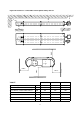
The maximum distance between supports is
1.5m for horizontal runs.
Wall bands are not load bearing and give lateral
support only. If used, wall bands should be fitted
every 3m on vertical runs to ensure the system
is rigidly held. The system should be braced
immediately below passing through the roof line
to ensure the flashing does not suffer lateral
pressures.
The maximum height unsupported above the
roof line is 1.5m. Where a joint is above the
roofline it should be determined that in extreme
wind conditions this joint would not be over
exerted. If there is any doubt then a guy wire
should be used. Beyond this guy wires should
be installed every meter.
The POCED is capable of withstanding its own
weight when installed in accordance with these
instructions and the Regulations shown below.
The exhaust flue should be adequately
supported from the building structure and
installed in accordance with the British
Standard Code of Practice BS 5440: Part 1 –
Installation and maintenance of flues and
ventilation for gas appliances of rated input not
exceeding 70kW net (1st, 2nd and 3rd family
gases), and the flue system manufacturers
instructions as supplied with the flue. See
reference BS 6896. Condensate drain pipes
must be protected against the effects of
freezing.
1.10.3 Condensation
When designing the flue system the prevention
of the formation and entrapment of
condensation must be a key consideration.
Horizontal flue should be fitted ensuring a slight
gradient approx 5
°
towards the terminal. Where
condensation is unavoidable traps should be
included to encourage the condensates to flow
freely to a point from which they may be
released, preferably into a gully. The
condensate pipe from the flue to the disposal
point must be made from corrosion resistant
pipe of not less than 25mm internal diameter.
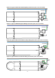
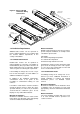
1.10.4 Method of Jointing Tube
1.10.4.1 Option 1 and 3
All pipe lengths and flue gas carrying
components are joined together by a twist lock,
bayonet system. The system should be installed
with the visible male collar pointing upwards,
this is reaffirmed by the directional arrow
pointing upwards, indicating the directional flow
of flue gases. Taping of the joints is
unnecessary.
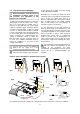
1.10.4.2 Option 2 Tailpipe
After allowing for a minimum of 75mm (3in) of
penetration of the fitting into the tube, cut the
tubes to the lengths required and remove all
burrs and wipe off any grease or oil with a clean
rag.
The components are joined by pushing the male
spigot and female socket together until the stop
is reached.
To seal use an applicator gun and apply a 4mm
diameter bead of high temperature silicon
jointing compound externally round the end of
the male spigot and internally round the end of
the female socket.
Push the male spigot into the female socket
using a slight rotating movement to spread the
jointing compound uniformly until a penetration
of 75mm (3in) is achieved.
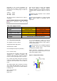
Note The silicon jointing compound remains
workable after application for only 5 minutes
Secure the joint by drilling through the tube and
fitting and fix with three pop rivets at 12 o’clock,
4 o’clock and 8 o’clock positions. 4.8mm
(3/16in) diameter pop rivets are recommended.
1.10.4.3 Option 5
The components are joined by pushing the male
spigot and female socket together until the stop
is reached. No sealant is required, but can be
applied if the formation of condensation is
anticipated.
To seal use an applicator gun and apply a 4mm
diameter bead of high temperature silicon
jointing compound externally round the end of
the male spigot and internally round the end of
the female socket.
Push the male spigot into the female socket
using a slight rotating movement to spread the
jointing compound uniformly until both fittings
have fully engaged.
Note The silicon jointing compound remains
workable after application for only 5 minutes