
Operating instructions


18
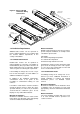
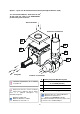
1.10 Flue and Combustion Air Inlet -
Options
Dependent on the type of burner fitted to your
heater it is possible to have configurations of
flue and combustion air inlet options to those
shown overleaf:
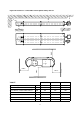
• Option 1
For induced burner with / without flue and / or
optional ducted air inlet refer to Figure 10.a
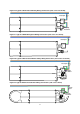
• Option 2
For herringbone heaters refer to Figure 10.b
& section 1.5 Herringbone Systems (UH/LH).
• Option 3
For forced burner with / without flue and
ducted air inlet refer to 10.c
• Option 4
For ducted air and products of combustion to
ventilated area please refer to Figure 10.c. &
10.d.
• Option 5
For flued products of combustion and ducted
air via concentric pipe please refer to Figure
10.e.
1.10.1 Important Information
1.10.1.1 Option 1 and 3
A suitable flue system complying with EN1856-1
(type T250 N1 D Vm L11040 O50) should be
used.
Flue size 125mm diameter twin wall.
Flue systems can run either vertically or
horizontally up to a maximum length of 9.5m
(including up to 2 x 90° bends plus the
terminal).
The minimum flue length shall be 1m.
The flue system must be terminated in a
vertical position and in accordance with the
British Standard Code of Practice BS 5440: Part
1 - Installation and maintenance of flues and
ventilation for gas appliances of rated input not
exceeding 70kW net (1st, 2nd and 3rd family
gases), and the flue system manufacturers
instructions as supplied with the flue.
1.10.1.2 Option 2
The tailpipe as supplied by the manufacturer is
to be used and installed as per the
manufacturers design drawing.
A suitable flue system complying with EN1856-1
(type T250 N1 D Vm L11040 O50) may be used
as an alternative to that offered by the
manufacturer.
Flue systems can run either vertically or
horizontally up to a maximum length of 9.0m
(including up to 2 x 90° bends plus the terminal).
The minimum flue length shall be 1m.
The flue system may be terminated vertically
or horizontally but in accordance with the
British Standard Code of Practice BS 5440: Part
1 - Installation and maintenance of flues and
ventilation for gas appliances of rated input not
exceeding 70kW net (1st, 2nd and 3rd family
gases), and the flue system manufacturers
instructions as supplied with the flue.
1.10.1.3 Option 5
A suitable flue system complying with EN1865-1
(type T200 P1 W V2 L50050 O00) should be
used.
Flue size 100mm diameter single wall.
The maximum flue length shall be 9.0m
(including up to 2 x 90° bends plus the terminal).
The minimum flue length shall be 1m.
The flue system must be terminated vertically
only and in accordance with the British
Standard Code of Practice BS 5440: Part 1 -
Installation and maintenance of flues and
ventilation for gas appliances of rated input not
exceeding 70kW net (1st, 2nd and 3rd family
gases), and the flue system manufacturers
instructions as supplied with the flue.
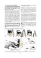
1.10.2 Installation
Connection to an appliance which is not
connected to the fuel supply may be carried out
by a competent person. However, connection to
an appliance that is connected to the fuel supply
must
be carried out by a registered installer.
If the flue passes through a wall, ceiling, or roof
made from combustible material then it has to
be sleeved so as to provide a minimum of a
50mm void between the exterior of the flue and
the internal wall of the sleeve. A minimum of
50mm must be maintained as a clearance
distance to all other combustible materials.
The manifold should be supported by chain,
stainless steel flexible wire, or other flexible
means from the roof structure to allow
movement caused by thermal expansion.