
Operating instructions


13
to the heater not to apply excessive turning
force to the internal controls.
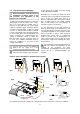
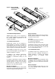
A flexible hose is installed to allow safe linear
expansion of the heater without creating undue
stress on the gas supply pipe work. It is
therefore important that a tested and certified
hose assembly made to ISO 10380, supplied
with ½” BSP female cone seat adapters, is
installed as per these instructions.
It is also important to ensure that expansion is
taken up in the body of the flexible hose, and
not on its attachment to the pipe work. The cone
seat adapter supplied on one end of the flexible
gas hose provides a `swivel` action, and must
be fitted on the burner using a ½” BSP barrel
nipple to provide ease of disconnection for
future servicing. This assumes that the heater
and fixed gas supply to the isolating valve have
been installed.
The installation layout described below is
the only method recommended by the
institute of gas engineers, the hose
manufacturer, and AmbiRad and must only be
carried out by a qualified/competent gas
engineer.
fig.a
fig.c
x
x
fig.b
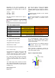
1.7 Gas Connection and Supply
Before installation, check that the local
distribution conditions, nature of gas
and pressure, and adjustment of the
appliance are compatible.
A competent or qualified engineer is required to
either install a new gas meter to the service
pipe or to check that the existing meter is
adequate to deal with the rate of gas supply
required. Installation pipes should be fitted in
accordance with BS 6896, so that the supply
pressure, as stated in Table 4 will be achieved.
It is the responsibility of the competent engineer
to ensure that other relevant Standards and
Codes of Practice are complied with in the
country of installation. Pipes of smaller size
than the heater inlet gas connection must not
be used. The complete installation must be
tested for soundness as described in the
country of installation.
The gas union service cock MUST be
fitted in the gas supply close to the
heater, but not onto the burner itself.
Take care when making a gas connection
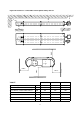
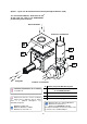
Figure 6. Correct Installation of Flexible Gas Connection
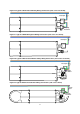
The methods shown in fig.e and fig.f are unacceptable, due to undue stress on the hose & fittings.
fig.e
fig.f
Arrow
denotes direction
of expansion.
fig.d
300
+/- 50mm
50
+/- 20mm