ASSEMBLY, INSTALLATION & SERVICING MANUAL AMBIRAD VISION® VSO & VSXO RANGE OF RADIANT TUBE HEATERS FOR INDEX Section Introduction and Document Index Installation Requirements -------------------------------------------------1 Assembly Instructions------------------------------------------------------2 Commissioning Instructions ----------------------------------------------3 Servicing Instructions ------------------------------------------------------4 Spare Parts --------------------------------------
Introduction. Welcome to the new range of high efficiency AmbiRad Vision radiant tube heaters. Local regulations may vary in the country of use and it is the installers responsibility to ensure that such regulations are satisfied. and attention is required to ensure that working at height regulations are adhered to at the mounting heights specified. PLEASE READ this document prior to installation to familiarise yourself with the components and tools you require at the various stages of assembly.
1. Installation Requirements. Isolate any electrical supply to the heater and controller before proceeding. 1.1 Health and Safety If there are any doubts as to the strength or suitability of roof steelwork to which heaters are to be suspended, please refer to a Consultant, Architect or owner of the building. The minimum mounting heights for AmbiRad heaters are given in the table below.
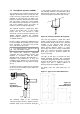
* * These angles to be equal and not more than 45°. Vertical suspension chain ideal. Where supports are inclined, maximum recommended angle of inclination is 15°. 5 Typical Speedlink attachment. Shackle method of attachment. Pin must be tightened by pliers. Drop rod with formed hook. note. hook or eyebolt must be closed tight. ON U TUBE VARIANTS THE HEATER SHOULD SLOPE DOWNWARDS TOWARDS THE RETURN BEND BY APPROX. 10mm FOR BOTH HORIZONTAL AND WALL MOUNTED INSTALLATIONS.
1.5 ‘U’ trap shall be 457mm deep. The end cap of the collecting chamber to be fitted with a flush flanged tank connector. Any protrusion to be removed leaving the inside flush with end cap. Herringbone Systems (VSOUH). The manifold system should be arranged to fall slightly in the direction of the vacuum fan. This ensures that any condensation formed in the manifold on cold start and cool down is not trapped or allowed to drain back into the heater unit.
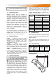
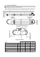
305.0 For details of fan mounting bracket and fixing down holes see figure 3. Figure 2g. Stainless Steel Telescopic Through The Wall Arrangement (available for Type ‘O’ and Type ‘2’ fans) Where a conventional flue is to be installed, AmbiRad supply an aluminium transformation piece to which a 150mm (6ins) diameter flue must be attached. Figure 2e. Conventional Flue Arrangement Roof Exit. The length of flue which may be connected to the fan outlet must be adequately supported from the building structure.
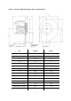
Figure 3. Vacuum Fan Mounting Details (Type ‘O’ fan illustrated) Hole Centers Fig 2c/d Hole Centers Fan Type O Type 2 A 124 80 B 38 35 C 175 174 D 7.1 7 E 209 125 F 153 100 G 42 25 H 239 120 J 340 210 K 332 205 L 363 215 Power (watts) 550 120 Running Current (amps) 2.6 0.8 Starting Current (amps) 15.4 4.
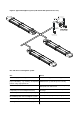
Figure 4. Typical Herringbone system (VSO shown with optional end covers) Dos and don'ts of herringbone system Dos Don’ts Check design pressure drop. Run drains in copper or mild steel pipework. Check for corrosive industrial process in Install system with extra 90° bends without asking proposed building - e.g. cleaning, electroplating, AmbiRad if the system will operate correctly. printers using sugar powder etc. Drain all flue ducts and seal all joints.
1.6 Clearance to Combustibles. The minimum clearances to combustible materials are given in the tables below. These minimum distances MUST be adhered to at all times. Figure 5.
Figure 5.
Figure 5.
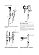
1.7 Gas Connection and Supply to the heater not to apply excessive turning force to the internal controls. Before installation, check that the local distribution conditions, nature of gas and pressure, and adjustment of the appliance are compatible. A flexible hose is installed to allow safe linear expansion of the heater without creating undue stress on the gas supply pipe work.
Depending on the specific installation, the flexible gas hose may be routed to the gas cock at any of the following angles in relation to the burner: Vertical 45° angle 90° angle Care must be taken to observe the minimum pipe bend diameter (minimum 250mm, maximum 350mm) & pipe expansion distance (minimum 30mm, maximum 70mm) as shown in fig.d. (fig.a) (fig.b) (fig.c) Maximum bend diameter for the 1000mm hose is 450mm. Any other position in between these angles is acceptable.
Figure 7.b Typical VSOUT Induced Unitary Wiring Connections (end covers not shown) Fused Spur Fan plugs into burner Figure 7.c Typical VSOUH Herringbone Wiring Connections (end covers not shown) Fused Spur Figure 7.d Typical VSXO Powered Burner Unitary Wiring Connections (end covers not shown) Fused Spur Fan plugs into burner Figure 7.e Typical VSXO Powered burner Wiring Connections (end covers shown) Fused Spur Fan plugs into burner Figure 10. Internal Burner Wiring Diagram.
Figure 8. Internal Burner Wiring Diagram. FAN L GREY VACUUM SWITCH N SOLENOID VALVE N.C. C. N.O. GREEN/YELLOW VALVE J.S.T. 2 1 3 BLUE EMC FILTER GRN/YLW MAINS INPUT N L BLUE BLUE BLUE MAINS ON GRN/YEL BROWN BROWN 1 2 WHITE MAIN J.S.T.
Figure 9. Typical VSO UH Schematic Wiring Connections 1 phase 230V Exhaust Fan Isolator Tail Pipe Isolator Isolator 0.75mm² Screened Cable Isolator Sensor Zone A Isolator 230V 50Hz 13A Controller Mains Supply 1.
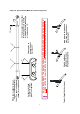
Flue systems can run either vertically or horizontally up to a maximum length of 9.0m (including up to 2 x 90° bends plus the terminal). 1.10 Flue and Combustion Air Inlet Options Dependent on the type of burner fitted to your heater it is possible to have configurations of flue and combustion air inlet options to those shown overleaf: The minimum flue length shall be 1m.
The maximum distance between supports is 1.5m for horizontal runs. with the visible male collar pointing upwards, this is reaffirmed by the directional arrow pointing upwards, indicating the directional flow of flue gases. Taping of the joints is unnecessary. Wall bands are not load bearing and give lateral support only. If used, wall bands should be fitted every 3m on vertical runs to ensure the system is rigidly held.
Option 1 - Figure 10a. Air Inlet Attachments Unitary Herringbone Burners (VSO) For non-flued installations, delete items A and For non-flued installations, delete items A and B and rotate fan outlet to the HORIZONTAL B and rotate fan outlet to the HORIZONTAL position away from the burner. position away from the burner. Ducted Air Intake Products of Combustion D A E B C Firing tube Products of combustion Ventilation requirements are as detailed in section 1.
Option 2 - Figure 10b. Air Inlet Attachments Induced Herringbone Burners (VSO) Ducted Air Intake C B A D Firing tube Products of Combustion Ventilation requirements are as detailed in section 1.9 Ducted air must be used in locations where there is airborne dust or where there is a polluted atmosphere e.g. Chlorinated Vapours. Maximum length = 9m Minimum diameter = 100mm Maximum no of bends = 2 21 A Induced Burner B Air Intake (supplied as standard) C Optional Ducted Air Intake.
Option 3 - Figure 10c. Forced Burner with Heat Exchanger (VSXO Standard Flue) For flued products of combustion and no ducted air Products of combustion L J K G G E H Air Inlet Firing tube G F Products of combustion Maximum flue length = 9.5m @ Ø125mm Maximum no of bends = 2 All flues must terminate vertically. For further information on flue runs, please refer to section 1.10.1 and BS 5440 pt.
Option 4 - Figure 10d. Forced Burner with Heat Exchanger (VSXO No External Flue) For ducted air and products of combustion to ventilated area J Fresh Air M G Products of combustion to ventilated area E G H G Firing tube F Products of combustion Ventilation requirements are as detailed in section 1.9 E Forced Burner F Heat Exchanger G 100mm (4ins) Clips x2 Ducted air must be used in locations where there is airborne dust or where there is a polluted atmosphere e.g. Chlorinated Vapours.
Option 5 - Figure 10e. Forced Burner with Heat Exchanger (with Concentric Flue) For flued products of combustion and ducted air via concentric pipe. Products of combustion IMPORTANT NOTE This option is a type B23 flue system with ducted air and is not a room sealed balanced flue product. Fresh Air Inlet P G J Fresh Air Products of combustion G N E H G Firing Tube F Ventilation requirements are as detailed in section 1.
1.11 Technical Details. No of Injectors 1 Gas Connection ½ in BSP Internal thread Flue Nominal Bore mm (in) 125 (5) Unitary Fan Motor Details 230 volt 1 phase 50Hz Table 5. Burner Settings - Natural Gas (G20) Heater Model Gas Injector Injector Flowrate Pressure Size Nett (m³/hr) (mbar) (mm) Heat Input kW Gross *Size (h x l x w) Fan Fan *Weight Rating Type (Kg) (A) VSXO20UT 20.0 18.0 1.9 9.2 7 x 1.7 445x4120x826 104 1.0 2507 VSXO25UT 25.0 22.5 2.4 10.0 7 x 1.
Table 6. Induced VSO Herringbone Settings - Natural Gas (G20) Heater Model Cold HB Pressure Hot HB Pressure mm H2O mbar mm H2O mbar VSO15UH 14.3 1.4 10.2 1.0 VSO20UH 18.4 1.8 10.2 1.0 VSO25UH 25.5 2.5 17.3 1.7 VSO30UH 14.3 1.4 10.2 1.0 VSO35UH 22.4 2.2 16.3 1.6 VSO40UH 20.4 2.0 17.3 1.7 VSO45UH 33.6 3.2 22.4 2.2 VSO50UH 33.6 3.2 22.4 2.2 Table 7.
Tables 8. Burner Settings - Propane Gas (G31) Heater Model Injector Injector Flowrate Pressure Size (l/hr) Nett (mbar) (mm) Heat Input kW Gross Fan *Weight Rating (Kg) (A) *Size (h x l x w) Fan Type VSO15UT 15.0 13.9 2.18 13.5 7 x 1.0 298x4049x826 97 0.5 2501 VSO20UT 20.0 18.5 2.88 12.4 7 x 1.2 298x4049x826 97 1.0 2507 VSO25UT 25.0 23.1 3.60 13.3 7 x 1.3 298x4049x826 97 1.0 2507 VSO30UT 32.0 29.6 4.60 22.5 7 x 1.3 298x5884x826 135 0.5 2560 VSO35UT 36.0 33.
Table 10. Flue details - Propane Gas (G31) Mass Flow Rate of Flue Gasses (kg/s) Flue Pressure (Pa) Maximum Flue Resistance Flue Gas Temp (°C) VSO15UT 0.0152 12.5 182 VSO20UT 0.0200 24.9 214 VSO25UT 0.0196 15.0 232 VSO30UT 0.0201 16.2 210 VSO35UT 0.0238 27.4 240 VSO40UT 0.0255 29.9 247 VSO45UT 0.0210 31.4 233 VSO50UT 0.0334 43.
2. Assembly Instructions. PLEASE READ this section prior assembly to familiarise yourself with components and tools you require at various stages of assembly. Carefully open packaging and check the contents against parts and check list. to the the the the Please ensure that all packaging is disposed of in a safe environmentally friendly way. For your own safety we recommend the use of safety boots and leather faced gloves when handling sharp or heavy items.
All remaining ‘U’ bolts on the RETURN TUBE should also be tightened to achieve a minimum torque setting of 15Nm². 2.2.4 Couplers For fixing the U bend. Locate and position tube couplers (D) Slide the coupler over the components ensuring that the rivet stop has butted up to the tube end and the pre-fitted bolts engage in the pre-cut holes so that the socket heads are FACING INWARDS.
B 3040mm TURBULATOR B FOUR MODULE A 976mm TURBULATOR B 1235 CRS. B 2600mm TURBULATOR B THREE MODULE A 976mm TURBULATOR B 1235 CRS. B 3400mm TURBULATOR B TWO MODULE A 976mm TURBULATOR B 1200 CRS. 3065mm TUBE 3065mm TUBE 1235 CRS. 2535mm TUBE B A 1795 CRS. C 3400mm TUBE 3400mm TUBE 1785 CRS. A B C C DETAIL B 3400mm TURBULATOR (NOT PROPANE) 1235 CRS. 5220mm TUBE 2535mm TUBE 1785 CRS. 2600mm TURBULATOR BURNER END 1120 CRS.
2.2.7.1 Overshield Reflectors 2.2.6 U Bend. Slide U bend (C) into the open end of the couplers ensuring the pre-fitted bolts engage in the precut holes. Tighten all four clamping bolts to provide a tight grip between tubes & U bend. To avoid damaging the heater whilst installing we recommend the heater chassis be suspended prior to fitting reflectors. 2.2.7 Reflectors There are three reflector section types used in the construction on the Vision Optima heater. 1. 2.
FOUR MODULE THREE MODULE TWO MODULE A A A A A A 1200 OVERSHIELD 201931 REFLECTOR #4 1200 OVERSHIELD 201931 REFLECTOR #3 1200 OVERSHIELD 201931 REFLECTOR #2 B B B B B B B B A A A A 1680 OVERSHIELD 201928 REFLECTOR #3 1680 OVERSHIELD 201928 REFLECTOR #2 1680 OVERSHIELD 201928 REFLECTOR #1 A A B B B B A A A A BURNER END 1680 OVERSHIELD 201928 REFLECTOR #2 1680 OVERSHIELD 201928 REFLECTOR #1 EXPANSION PLATE WASHER B B B B SET PIN A A BURNER EN
M8 bolt on the first bracket. Secure using large washers and anti vibration nuts. 2.2.7.2 Inner Reflectors All reflectors must be positioned/ attached to the brackets exactly as detailed in the assembly drawings. 3. The slot in other end of the first reflector should align with M8 bolt on the second bracket. Remove the protective plastic coating. 4. Locate the second reflector onto the same bolt using the FIRST slot in from the end and OVERLAP the first reflector. This should create a 77mm overlap.
2.2.8 Insulation mats. Ensure the 2nd reflector sits on top of the 1st. Using the recommended safety equipment i.e. gloves, goggles and a face mask, cover the back of reflectors with the insulation mats. Tuck in the edge of the mat behind the lip of the reflector. 5. Locate the M8 bolts on third bracket on this half to slot in same reflector approx one third distance from reflector end. Secure using large washers and anti vibration nuts.
FOUR MODULE THREE MODULE TWO MODULE 84mm OVERLAP 67mm OVERLAP 114mm OVERLAP 50mm OVERLAP 77mm OVERLAP 77mm OVERLAP WASHER REFLECTOR AV NUT WASHER REFLECTOR FIXING DETAIL- D Fig.
other and insert M8 self tapping screws provided. 2.2.9 Outer Canopy's 6. Repeat the procedure for 3rd set of outer canopies. 2.2.9.3 Four Module Units 1. Slide on the two halves to cover the centre section of the heaters and fit closing plates to each end (P). 2. Slide on two more outer canopies. Remove the protective plastic coating. 3. Stop short of the canopies already fitted and fit closing plates (P).
E 90mm OVERLAP 30mm OVERLAP 30mm OVERLAP SCRAP PLAN VIEW FROM ABOVE HEATER 30mm OVERLAP 30mm OVERLAP TWO MODULE SCRAP PLAN VIEW FROM ABOVE HEATER 30mm OVERLAP 55mm 35mm SCRAP PLAN VIEW FROM ABOVE HEATER FOUR MODULE THIRD CANOPY 15mm SCRAP VIEWS FROM ABOVE 15mm FOURTH CANOPY THREE MODULE *CANOPY FIXING FOUR MODULE ONLY POSITION E CANOPY FIXING DETAIL (EXCEPT *) Fig.
2.2.10 End Caps Remove the protective plastic coating. Position the end cap with no tube holes (M) beneath the reflector profile at the U bend end making sure that the end cap engages inside the inner reflector . Fasten to canopy using M5 pozi set pin and washers. 2.2.13 Fan Assembly On unitary heaters only, slide the fan assembly (E2) onto the LEFT HAND TUBE with the test point closest to the tube when viewed from behind ensuring it is fully engaged. Secure with pinch screws.
Manifold Tube Damper Blade Fitting Vacuum Test Point FLOW Emitter Tube External bead of jointing compound FLOW 2.2.15 Fixing of optional End Mouldings. Internal bead of jointing compound If end mouldings (P) have been ordered (optional item) fit the end mouldings with the screws provided / quick release clips to the holes in top of the canopy. Manifold Note The silicon jointing compound remains workable after application for only 5 minutes.
Radiant Tubes Suspension Brackets Return Bend Couplers Heat Exchanger (VXSO) Fan (unitary heaters) Damper (Herringbone) Forced Burner (VSXO) Induced Burner (VSO) Turbulators A B C D E1 E2 E3 F1 F2 G P Description N M Ref 41 G L J2 J1 J3 C D B A F1 Outer Canopy Canopy End Cap Closing Plates End Mouldings (optional) L M N P E3 Insulation K E2 Cross Member J3 E1 Expansion Plate J2 Overshields Reflectors Fig.
Ref Suspension Brackets Return Bend Couplers Heat Exchanger (VXSO) Fan (unitary heaters) Damper (Herringbone) Forced Burner (VSXO) Induced Burner (VSO) Turbulators C D E1 E2 E3 F1 F2 G Radiant Tubes Description N P M B A 42 J3 G J2 J1 L C D B Q H F1 Outer Canopy Canopy End Cap Closing Plates L M N E1 E2 F2 E3 Bellow coupler Insulation K Q Cross Member J3 End Mouldings (optional) Expansion Plate J2 P Overshields Fig.
Description Radiant Tubes Suspension Brackets Return Bend Couplers Heat Exchanger (VXSO) Fan (unitary heaters) Damper (Herringbone) Forced Burner (VSXO) Induced Burner (VSO) Turbulators A B C D E1 E2 E3 F1 F2 G N Ref 43 M P J1 G J2 J3 L C D B Q F1 E1 E2 E3 Bellow coupler Q F2 End Mouldings (optional) P Outer Canopy L Closing Plates Insulation K N Cross Member J3 Fig.
3. Commissioning Instructions. These appliances should be commissioned by a qualified engineer. 3.1 Tools Required. The following tools and equipment are advisable to complete the tasks laid out in this manual. Leather Faced Gloves Suitable alternative tools may be used. Large Adjustable Spanners or 22, 26 & 27mm Spanners for fitting Of Gas Flex. Wrench with Extension 3.
Slacken screw in burner lid and open the right hand burner access door. Connect extra sections of hose to each ‘T’ piece. The two vacuum impulse hoses are in view. Both hoses are fitted with ‘T’ pieces, one end of which has a blanking cap. Connect either a digital manometer or U tube gauge to the open ends of the hoses. Remove each blanking cap. Check reading against technical data.
3.3 Commissioning chart Check installation has been carried out to these instructions. Ensure gas and electricity supplies are isolated. Disconnect gas hose from burner Remove burner from tube and inspect burner head. (See servicing instructions) Reconnect gas hose. Open isolating valve. Check soundness. Replace burner on tube and secure. Open control housing and check that all components are securely fastened. Switch on electrical supply. The red neon should now be illuminated.
4. Servicing Instructions. These appliances should be serviced annually by a competent person to ensure safe and efficient operation. In exceptional dusty or polluted conditions more frequent servicing may be required. The manufacturer offers a maintenance service. Details available on request 4.1 Tools Required. Suitable alternative tools may be used. The following tools and equipment are advisable to complete the tasks laid out in this manual. Leather Faced Gloves 4mm Allen Key 12mm Spanner 4.
Figure 21. Forced Gas Burner: Model VSXO (refer to spares section 5) F Ignition Probes G Gas Valve H Multi Hole Injector A 2501/2507 or 2560 Fan I Neon's (Red/Amber) B Fan Inlet Spigot J Ignition Controller C Fan Orifice K Extrusion Burner Head D Fan Mount Plate L Pepperpot Head E Fan Mount Plate Gasket M Pressure Switch Please refer to spares for burner components J Jet Carrier 4.
Step 3 On forced burners with ducted air attachment, slacken jubilee clip and remove flexible hose from the fan. disconnected by separating the connectors of the ignition lead assembly and removing the pressure switch silicon tube. Step 4 Slacken both grub screws on the burner support casting using a 4mm Allen key to enable the burner to be removed from the radiant tube. Step 3 The gas injector can be inspected and replaced if contaminated or blocked.
Step 2 The pepper pot burner head can be replaced ensuring the 5 holes on the outer ring are aligned alongside the probes. Step 2 Loosen the 4mm grub screw and de-tatch the combustion fan. Step 3 The condition of the ignitor assembly can be checked for deterioration. However, we advise replacement at each service to ensure continued reliability. Step 4 Detach the electrode assembly from the burner head by removing the two screws and separating the ignitor lead connectors.
Step 4 Inspect the impeller and remove any dust with a soft brush. Step 5 Inspect the impeller and remove any dust with a soft brush. Step 5 Remove any dust from fan scroll and from around the motor. Step 6 Remove any dust from fan scroll and from around the motor. Step 6 Ensure the impeller rotates freely. Step 7 Refit components. 4.7 Combustion Fan Assembly Powered Burner Step 1 Slacken jubilee clip and remove the flexible hose from the fan. Step 7 Ensure the impeller rotates freely.
Step 4 Withdraw the turbulators from the appliance. Carefully noting their condition and position. Replace turbulators if necessary. Step 2 Slacken casing support screws and remove heat exchanger from the radiant tube. Step 3 Remove any dust and dirt from the heat exchanger & refit. Step 5 The turbulators should be cleaned with a soft brush. 4.10 Reflector Servicing The condition of the reflectors should be noted. If necessary the reflectors can be cleaned with a mild detergent.
5. Spare Parts. Required Spares (refer to section 4.2) In order to aid troubleshooting and servicing we recommend that the components shown in this section should be stocked. Note Any spare part components that are not approved by AmbiRad could invalidate the approval of the appliance and validity of the warranty. Item Item Description Part No. Ignition Controller 2015S Twin Gas Valve: Nat Gas Propane 201587 201914 Pepperpot Head Description Part No.
6. Fault Finding Guide. Ensure gas & electricity supplies are enabled. YES YES Does the RED neon illuminate? NO Check: 1. Burner controller 2. Red neon faulty Is there power on the burner? NO Check: 1. Operation of any thermostat 2. Any external fuses 3. Correct voltage is selected YES Does the combustion fan run? NO Check: 1. Wiring harness & plugs 2. Vacuum switch operation 3.
7. Replacing Parts. 7.1.1 Burner Controller Replacement (VSXO) 7.1.2 Burner Controller Replacement (VSO) Step 1 Slacken screw in burner lid and open the right hand burner access door. Step 1 Slacken screw in burner lid and open the right hand burner access door. Step 2 Undo 2 screws from controller bracket and remove. Disconnect burner controller from the wiring harness. Step 2 Disconnect burner controller from the wiring harness. Step 3 Disconnect the HT Lead from burner controller.
7.2 Air Pressure Switch Replacement 7.3 Gas Valve Replacement Step 1 Disconnect the two silicone impulse tubes and three wiring connections making note of replacement positions. Step 1 Remove the burner assembly as described in the section 4.3 Servicing. Step 3 Open the left hand access door and detach the impulse hoses from the air pressure switch. Step 2 Remove the two screws as shown below. Step 4 Remove the 4 screws holding the burner head onto the burner assembly.
Step 7 Remove the four screws holding the rear burner plate in position plus the two screws from the gas valve flange. Step 11 The gas valve can now be replaced. Step 12 Refit all components in reverse order. Step 13 (For Natural Gas burners ONLY). Ensure step screw is in the correct position as indicated in the diagram below. Step 8 Remove the rear plate. Step 14 Set gas pressures to data badge or as per section 1.11 and ensure reliable burner performance.
Notes 58
Notes 59
8. User & Operating Instructions. 8.1 To Start the Heater 8.3. Routine Maintenance between Service Intervals 1. Ensure gas supply is turned on. After ensuring that the heater is cold and mains electric isolated, cleaning of the reflectors with a soft cloth and a mild detergent (non solvent based cleaners only) in water can be undertaken. 2. Electrical supply to the controls is on. 3. Ensure that the controls are correctly set i.e.