
Specifications


8
MAIN J.S.T.
BROWN
GREY
BLACK
FLAME SENSOR
IGNITOR
8
7
9
1110 12
1
3
2
4
PURPLE
BLACK
LAMPS
ON
BURNER
YELLOW
GREY
BROWN
GREEN
BROWN
SOLENOID VALVE
SWITCH
N.C.
N.O.
C.
BROWN
BURNER
POWER INPUT
L
N
FAN
N
L
ON
POWER
WHITE
WHITE
WHITE
WHITE
WHITE
VACUUM
BROWN
1
3
2
VALVE
J.S.T.
GREEN
WHITE
GREEN
YELLOW
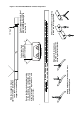
If any of the original wire as supplied with the appliance must be replaced, it must be replaced
with wiring material having a temperature rating of at least 220°F/105°C
Heater 1
Heater 2
Heater 3
Heater 4
Heater 5
Heater 6
Double pole insulator
adjacent to each
heater
Thermostats
Zone 1
Zone 2
Zone 1 Zone 2
Time
switch
Manual
switch
L
N
G
Frost Thermostat
120v
1ph 60Hz
(Two Zones)
*
*
*
Double pole
fuse isolator
{
Figure 7. External Wiring Schematic.
Figure 6. Internal Burner Wiring Diagram.