WARNING: Improper installation, adjustment, alteration, service or maintenance can cause property damage, injury or death. Read the installation, operating and maintenance instructions thoroughly before installing or servicing this equipment.
Introduction. Welcome to the new range of high efficiency AmbiRad VSXUS infra-red heaters. Local regulations may vary and it is the installer’s responsibility to ensure that such regulations are satisfied. and attention is required to ensure that working at height regulations are adhered to at the mounting heights specified. PLEASE READ this document prior to installation to familiarize yourself with the components and tools you require at the various stages of assembly.
1. Installation Requirements. D. E. 1.2 The unit shall be electrically grounded in accordance with National Electric Code ANSJJNFPA 70. The heater may be installed in aircraft hangars installed in accordance with the Standard for Aircraft Hangars, ANSI/ NFPA 409 and in automotive garages when installed in accordance with the Standard for Parking Structures, ANSI/ NFPA 88A, or the Standard for Repair Garages, ANSI/NFPA 88B, and are so marked.
* * * VSX models Vertical orinclined suspension on this plane is acceptable. * * 4 Vertical suspension chain ideal. Where supports are inclined max. recommended angle of inclination 15° 15° max Shackle method of attachment. Pin must be tightened by pliers Drop rod with formed hook. n.b. hook or eyebolt must be closed tight after installation. Alternative method of suspending ‘U’ tube and linier type heaters. IMPORTANT: THE HEATER SHOULD SLOPE DOWNWARDS TOWARDS THE RETURN BEND BY APPROX.
1.5 IMPORTANT: The stated clearance to combustibles represents a surface temperature of 90°F (32°C) above room temperature. Building material with a low heat tolerance may be subject to degradation at lower temperatures. It is the installer’s responsibility to assure that adjacent material are not subject to degradation. Clearance to Combustibles. The minimum clearances to combustible materials are given in the tables below. These minimum distances MUST be adhered to at all times.
1.6 Figure 3. Correct orientation of Ball Valve Gas Connection and Supply WARNING: Before installation, check that the local distribution conditions, nature of gas and pressure, and adjustment of the appliance are compatible. Gas Flow The gas connection on the heater is ½”N.P.T external thread. Gas Flow Injector sizes and manifold pressure for the burners are shown in the table 3. The gas supply piping and connections must be installed so that the minimum pressure stated is achieved. Figure 4.
WARNING: FIRE OR EXPLOSION HAZARD - Expansion of the radiant pipe occurs with each firing cycle causing the burner to move with respect to the gas line. This can result in a gas leak producing an unsafe condition. It is therefore essential to provide some flexibility in the final gas line connection by use of an approved armoured flexible connector or stainless steel expansion loop as shown in the drawings. Table 3 Gas Supply Pressures Natural Gas Gas Type Required Gas Pressure (in W.C) 7.
Figure 6. Internal Burner Wiring Diagram. FAN L BROWN VACUUM SWITCH N SOLENOID VALVE N.C. C. N.O. GREEN 2 1 3 BURNER POWER INPUT WHITE VALVE J.S.T. GREEN N L WHITE WHITE WHITE BURNER ON POWER ON GREEN WHITE BROWN BROWN 1 2 BLACK MAIN J.S.T.
Standard vent terminals must extend at least 6” from the wall and at least 24” from any combustible overhang. Protect the building material from degradation by the vent gasses. 1.8 Vent Requirements and Details 1.8.1 Unvented units Heaters maybe installed without a vent providing the governing building codes are met and consideration is properly given to possibilities of condensation on cold surfaces.
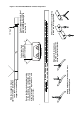
Figure 8.a Fresh Air Ducted Intake. 4" O.D. PIPE MAX LENGTH = 25'-0" WITH 2-90° LONG RADIUS BENDS 90° BEND 4" O.D. HIGH TEMP. FLEXIBLE DUCT CLAMPS REFLECTOR HEAT EXCHANGER Figure 8.b Wall Terminal Intake Kit. 36" MIN CENTERS TERMINAL WALL INLET WITH BIRD SCREEN SEAL JOINTS WITH SILICONE OR DUCT TAPE 6" 1.9 Vent and Combustion Air Inlet Options • Option 2 For ducted air and products of combustion to ventilated area please refer to Figure 8.f.
Figure 8.c Vertical Venting. SUPPLIED BY OTHERS CODE APPROVED VENT THROUGH ROOF ROOF SEAL SEAL JOINTS WITH HIGH TEMPERATURE SILICONE 4" O.D. OR 6" O.D. FLUE 12'-0" 12'-0" (APPROXIMATE MAXIMUM DIMENSIONS) 4" TO 6"DIA. ALUMINIUM ADAPTER (REQUIRED ONLY FOR 6" DIA. VENT) 4" O.D. HIGH TEMP. FLEXIBLE DUCT CLAMPS REFLECTOR HEAT EXCHANGER Figure 8.d Horizontal Venting. SEAL JOINTS WITH HIGH TEMPERATURE SILICONE 6" CODE APPROVED VENT TERMINAL 90° BEND WALL COLLAR 4" TO 6"DIA.
Option 1 - Figure 8.e. Forced Burner with Heat Exchanger (Standard Vent) For vented products of combustion and no ducted air Products of combustion Air Inlet Firing tube Products of combustion If heaters are installed with no vent the ventilation instructions detailed in section 1.8 must be applied. Ducted air must be used in locations where there is airborne dust or where there is a polluted atmosphere e.g. Chlorinated Vapours.
Option 2 - Figure 8.f. Forced Burner with Heat Exchanger (No External Venting) For ducted air and products of combustion to ventilated area Fresh Air Products of combustion to ventilated area Firing tube Products of combustion if heaters are installed with no vent the ventilation instructions detailed in section 1.8 must be applied. Ducted air must be used in locations where there is airborne dust or where there is a polluted atmosphere e.g. Chlorinated Vapours.
Option 3 - Figure 8.g. Forced Burner with Heat Exchanger (with Concentric vent) For vented products of combustion and ducted air via concentric pipe 10ins Products of combustion 9ins 23ins 54ins Fresh Air Inlet Fresh Air Products of combustion Firing Tube Products of combustion if heaters are installed with no vent the ventilation instructions detailed in section 1.8 must be applied. Ducted air must be used in locations where there is airborne dust or where there is a polluted atmosphere e.g.
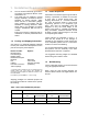
1.10 Technical Details Table 4 - Technical Details. All heaters to run on Natural Gas (G20) 1 No of Injectors Gas Connection ½” N.P.T nipple. Electrical Supply 120 volt 1 phase 60Hz 4” or 6” Vent size (in) 120 volt 1 phase 60Hz Unitary Fan Motor Details 1.2A MAX Current Rating Electronic Program Start up with Spark Ignition Ignition Burner Size Nominal Gross Heat Burner Head Burner Orifice Plate Injector Injector Pressure BTU/Hr Part No. Part No. Part No. Inches WG.
2.2 Identification check list COLOUR CODE VSX90 VSX140 1x 1x 1x 1x 1x 1x COLOUR CODE Inner End Caps Burner Outer Canopy End Caps Heat Exchanger 2x 2x 2x 2x 2x 2x 2x 3x 2x 3x 2x 2x 1x 2x 7 8 13 14 2 4 16 22 6 8 Turbulators 2x 3x Outer Canopy Couplers 3x 4x 12 16 M4 Full Nut Brackets M4 Washer M6 Mudwasher 4 6 6 10 No.
2.3 Prior to assembly • Ensure the area in which you are working is safe and clear of obstructions. • Identify with the components in the check list and in which order they will be assembled. • Arrange the trestles* in a straight line to allow for length of tubes. • Remove all protective plastic from underside of Stainless Steel Reflectors / inside of End Caps. * if saw horses cannot be located, ensure any alternative is sound and can carry the heater weight.
4 Working at the opposite ends of the tubes to the burner, locate & position two couplers so that the socket heads are facing outwards & the pre-fitted bolts in the couplers line up with the locating holes in the tubes. Do not fully tighten at this stage. 2x 2x 5 Slide U bend into the open end of the couplers ensuring the pre-fitted bolts engage in the pre-cut holes in the U tube section. Tighten all four clamping bolts to provide a tight grip between tubes & U tube section. 1x 1x 2.4.
8 Slide 2nd bracket to line up with innermost slotted hole in 1st reflector, & bolt together using M6 x 35mm pins, washers & nuts. Bolt 1st & 2nd reflectors together using end elongated holes in each. 4x 4x 9 Repeat this procedure referring to the assembly diagram for quantities used on specific models, but noting that the final bracket is not bolted to the reflector. (See photo) At this stage all the U bolts should be fully tightened.
2.4.5 CANOPIES 13 Remove protective film before starting. Slide the outer canopies over the reflectors from the U bend end ensuring correct location in reflector profile. Line up burner end canopy flush with burner end reflector. Overlap canopies as shown in the assembly diagram. 2x 3x CAUTION — SHARP EDGES! 14 Adjust canopies so that the holes on top align with each other as detailed in the assembly instructions. Locate and fix one No.5 torque screw on every canopy overlap. 1x 2x 2.4.
Figure 9. VSXUS Heater Assembly 2.4.8 Detailed Assembly Drawings INSERT # 201705 VSXUS90 21 3400 TURBULATOR Please note the heater type, length and reference number from the delivery/advice note before identifying the correct model drawing. The following pages show the technical dimensional details of the VSXUS range of heaters.
2600 TURBULATOR 976 TURBULATOR VSXUS140 2600 TURBULATOR
Figure 10.
3. Start Up Instructions. These appliances should be commissioned by a qualified mechanical contractor. 3.1 Tools Required. The following tools and equipment are advisable to complete the tasks laid out in this manual. Leather Faced Gloves Small Flat Head Screwdriver Phillips Screwdriver ½” Spanner 3.2 Suitable alternative tools may be used. 5/32” (4mm) Allen Wrench Manometer Large Adjustable Wrenches for fitting Of Gas Flex. Multimeter producing a spark at the ignition electrode.
should attempt to relight and if the gas valve has been left off ‘lock-out’ should occur indicated by the ‘power on’ lamp being illuminated and fan running, but the ‘burner on’ lamp being off. With the heater running normally, pull off the silicone rubber tube connecting the vacuum switch to the combustion chamber. Within 4 seconds the burner should shut off. Then replace the tube securely and observe that the heater proceeds to ignite in the normal way.
4. Servicing Instructions. These appliances should be serviced annually by a competent person to ensure safe and efficient operation. In exceptional dusty or polluted conditions more frequent servicing may be required. Servicing work should be carried out by a qualified mechanical contractor. 4.1 Tools Required. Suitable alternative tools may be used. The following tools and equipment are advisable to complete the tasks laid out in this manual. 4.
4.3 Burner Removal Step 1 Isolate power and gas supplies. Step 2 Unplug the power connectors. Step 5 Slacken the set screw on the burner support casting to enable the burner to be removed from the radiant tube. Step 6 Remove the burner and position the burner in a safe area to prevent the burner or components attached to the burner from falling to the ground. Step 3 Detach the gas supply as shown below, taking care to support the burner connection.
replaced ensuring the 5 holes on the outer ring are aligned alongside the probes. Step 2 The gas injector can be inspected and replaced if contaminated or blocked. Step 3 The condition of the igniter assembly can be checked for deterioration. However, we advise replacement at each service to ensure continued reliability. Detach the electrode assembly from the burner head by removing the two screws and separating the igniter lead connectors.
4.6 Combustion Fan Assembly Step 1 If ducted air is fitted, slacken hose clamp and remove the flexible hose from the fan. Step 7 Ensure the impeller rotates freely. Step 8 Refit components. Step 2 Remove fan screws and unplug from burner box. 4.7 Radiant Tube Servicing Step 1 Brush any dust from the exterior of the tubes. Step 2 Inspect the fan and burner tubes visually. If the tubes appear clean, skip to servicing the reflector. Step 3 Remove the U bend. Step 3 The combustion fan can now be detached.
If necessary the reflectors can be cleaned with a mild detergent. This can significantly improve the efficiency of the appliance. 4.10 Sweeping of Vent Inspect the fresh air inlet duct and vent to ensure they are free from any blockage or obstruction. The air inlet terminal and vent terminal should be inspected to ensure they are not liable to obstruction. Step 3 If required the interior of the tubes can then be cleaned using an industrial vacuum cleaner or by using long poles and a scraper. 4.
5. Spare Parts. Required Spares Note Any spare part components that are not approved by AmbiRad could invalidate the approval of the appliance and validity of the warranty. In order to aid troubleshooting and servicing we recommend that the components shown in this section should be stocked. Item Description Part No. Ignition Controller Item Description Part No.
6. Troubleshooting Guide. Ensure gas & electricity supplies are enabled. YES YES Does the RED neon illuminate? NO Is there power on the burner? NO YES Does the Fan run? NO Check: 1. Wiring harness & plugs 2. Vacuum switch operation 3. Replace fan NO NO If the heater still fails to operate normally, please contact your local representative. Check: 1. Vacuum switch tubes 2. Emitter tubes, air inlet & vent for obstructions 3. Operation of vacuum switch 4. Replace fan Check: 1.
7. Replacing Parts. 7.2 Air Pressure Switch Replacement Turn of gas any electrical supplies to the heater before starting repair work.. Step 1 Open left hand door. Disconnect the two silicone impulse tubes. 7.1 Burner Controller Replacement Step 1 Slacken screw in burner lid and open the right hand burner access door. Step 2 Disconnect burner controller from the wiring harness. Step 2 Remove the two screws as shown below.
7.3 Gas Valve Replacement Step 1 Remove the burner assembly as described in the Servicing Sections. Step 6 Detach the two screws holding the front of the gas valve. Step 2 Open the right hand access door and detach the burner controller from the wiring harness. Step 7 Remove the four screws holding the rear burner plate in position. Step 3 Open the left hand access door and detach the impulse hoses from the air pressure switch. Step 8 Remove the rear plate.
THIS PAGE HAS INTENTIONALLY BEEN LEFT BLANK.
8. User & Operating Instructions. AmbiRad is the manufacturer of a series of tubular infra-red heaters designed for overhead heating of industrial and commercial buildings. Individual heating units are suspended from the roof or mounted at an angle on the wall 8.1 1. This appliance must only be installed by qualified craftsmen in accordance with the requirements of local and National Codes. 2. This appliance must be grounded in accordance with the National Electrical Code ANSI/NFPA No.70. 3.