
Installation and Operation Guide

TS-3000i Web Clock Installation & Operation Guide 2-11
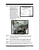
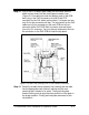
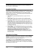
Step 12. Plug in the FPR battery pack cable (the connector with the
black and red wires) into the small open connector (see
Figure 2-13) located just under the battery pack on the PCB.
Next, plug in the PoE connector to the left of the FPR
connector for the PoE cable (yellow wires). It is keyed and can
only fit into the connector one way. The connection for the PoE
cable has a 5-pin connector on the main PCB and a 5-pin
connector at the PoE PCB. Both connector ends are keyed
(can only fit in one way). You may have to temporarily remove
the connector on the PoE PCB to install the top plate.
Figure 2-13: Rear View Showing PoE & FPR Cables/Connections
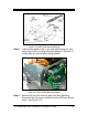
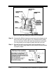
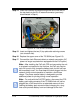
Step 13. Carefully reinstall the top plate by first inserting the rear tabs
into the appropriate rear notches, making sure the rear
centering tab is located in its notch. Then push the plate
forward making sure to align the sides and front of the plate in
the proper position. Finally push the plate downward to lock
into position.