
Installation and Operation Guide

2-4 TS-3000i Web Clock Installation & Operation Guide
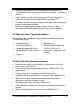
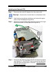
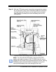
Step 5. Lift up the top plate by
pulling upwards and
towards the back of the
clock to remove it.
Temporarily set aside. Note
the alignment of the top
plate during removal –
especially the front and rear
tabs (see figure to the right).
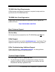
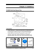
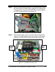
Step 6. Carefully lift the front PCB
up and out of its retaining
slot (see Figure 2-11). This
is the PCB with the coin
battery on it. Just lift the
PCB up enough to provide
adequate clearance for the
FPR mounting bracket to be
inserted into its side retaining slots on the right and left sides of
the main clock frame (see Figure 2-6).
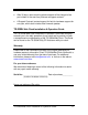
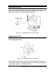
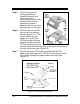
Step 7. Carefully insert the FPR mounting bracket with the FPR
battery pack (see Figure 2-5). It will fit only one way as it must
slip over the rectangular shaped network connector (see
Figure 2-7).
Figure 2-5: FPR & Mounting Bracket