TS-3000i® TimeSync Web Clock Installation and Operation Guide
Thank you… For purchasing another fine product from Amano Cincinnati, Inc. Proprietary Notice This document contains proprietary information and such information may not be reproduced in whole or in part without written permission from: Amano Cincinnati, Inc. 140 Harrison Avenue Roseland, New Jersey, 07068-1239 Amano Cincinnati, Inc. reserves the right to make equipment changes and improvements that may not be reflected in this document.
Table of Contents Chapter 1: Introduction .......................................................................1-1 How This Manual is Organized ..........................................................1-1 TS-3000i Web Clock General Information .........................................1-1 What is OATS Compliance? ..........................................................1-3 TS-3000i Web Clock Features ......................................................1-3 TS-3000i Web Clock Benefits...............
Table of Contents Chapter 4: TS-3000i Operation ...........................................................4-1 General Information............................................................................4-1 About Bonjour and Zero-Configuration ..........................................4-1 TS-3000i Web Interface .....................................................................4-3 TS-3000i Web Page ......................................................................4-3 Login ....................
Table of Contents Chapter 7: Maintenance.......................................................................7-1 TS-3000i Web Clock Diagnostics ......................................................7-1 How to Display Clock Configuration ...............................................7-1 How to Manually Time Sync the Clock ..........................................7-2 How to Perform LCD Display Clock Diagnostics ...........................7-3 How to Reset the Clock.....................................
This page intentionally left blank.
Chapter 1: Introduction How This Manual is Organized The installation, setup and operation procedures in this manual are provided for user assistance. Chapter 1 provides general information with a brief overview of features, and benefits. Chapter 2: provides an overview of system components with step-bystep procedures for installing your TS-3000i Web Clock. Chapter 3 provides step-by-step procedures for quick startup using a Web browser.
The TS-3000i Web Clock utilizes Zero Configuration Networking (Zeroconf), a set of techniques that will automatically create a usable network IP address without configuration or special services. This allows users to connect TS-3000i’s together and expect them to work automatically. Without Zeroconf, a user must either set up special services, like Dynamic Host Configuration Protocol (DHCP) and Domain Name System (DNS), or set up each device’s network settings manually.
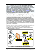
During the configuration process, both the event logger and scheduler use the same supporting configuration files located in the clock. The event logger runs in the clock with a scheduler that runs in the background as a service. The TS-3000i Web Clock can optionally obtain power from a Full Power Reserve (FPR) or Power over Ethernet (PoE) (see Figure 1-1).
Optional PoE (Power over Ethernet) accessory, which includes Full Power Reserve (FPR option). Automatic time synchronization to an official time source. Event notification through Simple Network Management Protocol (SNMP) traps. This feature enables network administrators to centrally manage time clock performance, find problems and solve them in a timely manner. NTP (Network Time Protocol) syncs clocks to a time reference over a data network.
Time sync transaction files are automatically maintained in the TS-3000i Web Clock and can be saved to file, viewed, or printed as desired. Visible alarms on time stamp imprint and LCD display provide notification of time synchronization failure (see Figure 7-8). Provides a solution for industry sectors that require strict adherence to good time keeping practices. No server software required, which means minimal IT staff involvement and lower support costs due to streamlined setup.
TS-3000i Web Clock Requirements A Web browser and Ethernet connection is required to setup and time synchronize the TS-3000i Web Clock. TS-3000i Web Clock Registration Please return the enclosed warranty registration card or register the product online at: http://www.amano.com/time Basic Customer Support On-Line Help On-line help can be accessed from the TS-3000i Web page Help link. E-Mail Support Support is provided via e-mail at atvs@amano.
After 30 days, users requiring phone support will be charged a fee per incident or the user can purchase a support contract. A Support Contract (contact support for fee) for hardware support for one year, which also includes free firmware updates. TS-3000i Web Clock Installation & Operation Guide The TS-3000i Web Clock Installation & Operation Guide was designed to assist you in the daily operation of your clock and to provide you with a comprehensive understanding of the TS-3000i Web Clock.
Time Servers General Information A time server is a server computer that reads the actual time from a reference clock and distributes this information to its clients using a computer network. The time server may be a local network time server or an Internet time server. The most important and widely-used protocol for distributing and synchronizing time is the Network Time Protocol (NTP), though other less-popular or outdated time protocols continue in use.
Chapter 2: Installation TS-3000i Web Clock External View 2-1 TS-3000i Web Clock External View Components • 2 Keys (Important!! - Please store these keys in a safe place as you will need them to remove the cover). One unit with attached AC power adapter and Ethernet cable (10ft) with RJ-45 connector. • A Utility CD for the clock (copy configuration to clocks, auto discovery, reports, etc.), which also contains the Installation and Operation Guide in PDF format. Also, Quick Start Guide (printed).
Removing the Cover Insert and turn the key clockwise to remove the upper cover. Note – the upper cover must be removed to change the ribbon and access the reset button (see Chapter 7, How to Replace the Ribbon). Figure 2-2: TS-3000i Web Clock Cover Removal Unpacking the Clock After removing the upper cover, lift up the Printer Block (A) and remove the Packaging Spacer (B).
Installing the Optional FPR Step 1. Disconnect the clock AC adapter from the power outlet. Warning! – Failure to do so could result in a hazardous shock. Step 2. Insert the key, turn the key clockwise, and remove the upper cover of the TS-3000i (see Figure 2-2). Step 3. Remove one small Phillips head retaining screw from the right and left front sides of the top plate (see Figure 2-4). Figure 2-4: Top Plate Removal Step 4.
Step 5. Lift up the top plate by pulling upwards and towards the back of the clock to remove it. Temporarily set aside. Note the alignment of the top plate during removal – especially the front and rear tabs (see figure to the right). Step 6. Carefully lift the front PCB up and out of its retaining slot (see Figure 2-11). This is the PCB with the coin battery on it.
Step 8. After the FPR mounting bracket is in its proper position, return the front PCB to its original position seated in its retaining slot. In this position the top rear of the PCB will fit close alongside the FPR mounting bracket (see Figure 2-6). Figure 2-6: Front PCB & FPR Mounting Bracket in Position Step 9. Install the two plastic rivets (1 per each side) as illustrated in Figure 2-7 through the side of the clock frame into the proper locating hole in the FPR mounting bracket (see Figure 2-5).
Step 10. With the FPR battery pack in the holder alongside the network RJ-45 connector, plug in the FPR battery cable (the connector with the black and red wires) into the open brown connector (see Figure 2-8) located just under the battery pack on the PCB at CN4. Figure 2-8: Rear View Showing Cable/Connector Location Note – For units with the FPR option, disconnect the FPR battery pack cable connector if the TS-3000i clock will not be plugged into AC power for an extended amount of time.
Step 11. Carefully reinstall the top plate by first inserting the rear tabs into the appropriate rear notches, making sure the rear centering tab is in its notch. Then push the plate forward (see righthand figure) while properly aligning the top plate sides and front. Finally push the top plate downward to lock it firmly into position with the front tabs (see Figure 2-9). Figure 2-9: Top Plate Installed Step 12.
Note – After installing the FPR and connecting the unit to AC power for the first time, allow it to charge the battery pack for 24 hours before printing. Failure to do so may result in reduced battery life. When using the optional FPR - keep the clock plugged into an AC power source during normal operation to maintain an adequate charge. The power reserve battery is designed to be used only during limited power outages, not as a power source during normal operation.
Figure 2-10: PoE/FPR & Mounting Bracket Step 8. Install the two plastic rivets (1 per each side) through the main clock frame into the locating holes as illustrated in Figure 2-10 to help align and secure the mounting bracket. Figure 2-11: Front PCB & Mounting Bracket Step 9. Remove the rear wall mounting plate (see Wall Mounting). Disconnect the AC power connector from the PCB (red & white wires – see Figure 2-12).
Figure 2-12: Rear View Showing AC Power Line For Removal Step 10. Unscrew the Phillips head screw and remove the black ground wire for the AC line (see Figure 2-12). Remove the AC power line from the back of the clock with the transformer at the end. You may have to cut a couple of plastic wire ties to do this. Step 11. Reinstall the wall mounting plate (see figure below) on the back of the clock using caution to verify that the Ethernet cable is properly routed.
Step 12. Plug in the FPR battery pack cable (the connector with the black and red wires) into the small open connector (see Figure 2-13) located just under the battery pack on the PCB. Next, plug in the PoE connector to the left of the FPR connector for the PoE cable (yellow wires). It is keyed and can only fit into the connector one way. The connection for the PoE cable has a 5-pin connector on the main PCB and a 5-pin connector at the PoE PCB. Both connector ends are keyed (can only fit in one way).
Step 14. Insert the Ethernet connector through the hole in the rear of the top plate into the RJ-45 network connector (previously disconnected in Step 4). Figure 2-14: PoE & FPR Connectors Step 15. Insert and tighten the two (2) top plate side retaining screws (one on each side). Step 16. Replace the upper cover of the TS-3000i (see Figure 2-2). Step 17. Connect the clock Ethernet cable to a network connection (AC power no longer required when equipped with the PoE option).
Note – For units with the PoE/FPR option, leaving the TS-3000i clock unplugged from a PoE terminal or without power for more than 24 hours may create a problem with the clock starting up (you will see “low bat” briefly appear in the display). In this instance, the clock should be started with the battery pack cable disconnected and the clock plugged into a PoE terminal. Wait until the clock starts up, or displays the time, then the battery pack cable can be reconnected and it will charge.
Wall Mounting Amano recommends the following procedure for wall mounting: Step 1. With the cover removed, the wall mount plate can be removed by using your index finger as shown to pry open the bottom portion (see arrow 1). Slide the wall mount plate down in the direction of arrow 2. Use caution not to disrupt the power and Ethernet cables on the back when removing the wall mount plate. Step 2. Knock out the three holes in the mounting plate. Step 3.
The First Printout Please verify the following before attempting to print: Step 1. Is all the packaging material removed from inside the clock? Step 2. Is the FPR battery connected? (optional) Step 3. Is the cover securely on the clock? Step 4. Is the TS-3000i Web Clock connected to a network connection (Ethernet RJ-45)? This step is not required to perform a test printout when first installing the TS-3000i Web Clock. Step 5.
Seconds must be selected to be printed for this error message to be seen. Seconds = default setting. Acceptable Print Media Print Media is defined as the type of material you will be using in the machine to time stamp (time cards, documents, etc.). To avoid damaging the print head, it is recommended that you do not exceed a media thickness of 0.3 mm (0.01"). The following are general specifications for the different media dimensions. Time Card: Time card thickness less than or equal to 0.3 mm (0.01").
Figure 2-17: TS-3000i Printer Adjustment Available Print Methods There are three different Print Methods available. The default Print Method is for Paper Detect Only (P.). If you wish to change the default Print Method, locate the Print Method Selector on the bottom of the machine (see Figure 2-17) and move it to the desired position. The settings are: P.
S. - Print Switch Only: This setting will allow you to print manually regardless of print margin setting by inserting media into the TS-3000i Web Clock and pressing the Print Bar. Warning! – Printing when no media is present may cause damage to the print head. Front Panel Reset Button The front panel (see Figure 2-18) reset button can be accessed by removing the upper cover (see Figure 2-2).
Specifications Power Requirements: 120 VAC ±10%, 60 Hz 100 and 230 VAC ±10%, 50/60 Hz Power Consumption: Normal 4.5W, Maximum 25W. Power Failure Memory Protection: Built-in lithium coin battery (up to 12 months). Communication: 10/100 BaseT (auto-sensing), RJ45 connection. Ambient Conditions: Temperature: -10°C to 45°C (14°F to 113°F) FPR Option: 0°C to 45°C (32°F to 113°F) Humidity: 10% to 90% (non condensing). Dimensions: 176 mm (6.9”) High X 150 mm (5.9”) Wide X 153 mm (6.0”) Deep.
Options Full Power Reserve (FPR): Optional, 9.6V, 700mAh NiCad rechargeable battery. When fully charged, it will maintain normal operations for 6 hours or 400 prints. Power over Ethernet (PoE): Optional, and includes 9.6V, 700mAh NiCad rechargeable battery. 48V in, 13.5V out Power over Ethernet Overview With the PoE Option for TS-3000i: Power-over-Ethernet (PoE) is a network standard based on IEEE 802.3af that provides a means of delivering power to devices connected to a LAN.
Chapter 3: Quick-Start Getting Started Amano recommends the following prerequisites: Ethernet connection (TS-3000i comes with 10 foot Cat5 cable) to connect the clock to for time sync and configuration. AC power (TS-3000i comes with 6 foot long cable attached to power adapter if not equipped with the PoE option). A web browser for configuring the TS-3000i. Amano recommends using the TS-3000i Utility CD which came packaged with the clock.
Note – Bonjour may have to be downloaded and installed into IE as a plug-in. Safari® with Bonjour: Start Safari browser and select the Bookmarks menu Show All Bookmarks. Double-click on the desired TS-3000i Web clock from the list of discovered Bonjour devices (see Figure 3-2). Figure 3-2: Using Safari with Bonjour to Find TS-3000i Web Clock Firefox without Bonjour: Use the TS-3000i Utility which is discussed in detail in Chapter 5 to discover and connect to the clock.
All of the discovered TS-3000i clocks will be displayed in a list with their Domain, Device Name, IP Address, MAC Address, and Status (see Figure 3-3). Go to View Clock Firmware version Show Version to see the clock firmware version. Figure 3-3: TS-3000i Utility Auto Discovery Step 2. Double-click on a clock from the list and your browser will open to the web login screen for that clock. See the following TS-3000i clock Login example.
Step 3. If this is your first time logging into the clock enter Username = Admin Password = 6569 If this is not your first time logging into the clock, enter your case-sensitive Username (maximum = 20 characters) and your Password (maximum = 15 characters), then click on the Login button and the TS-3000i Web Clock Information page will appear (see Figure 3-5). ONLY 1 user can be logged into a clock.
First Time Set up of the TS-3000i Web Clock Note – The TS-3000i Web Clock configuration parameters can be customized at any time and do not have to be done in the following order. Amano recommends setting up these parameters to obtain the full potential from you clock. Step 1. Log into the TS-3000i Web clock (see Figure 3-4) and Click on the Settings link under Users, and the Users List screen will appear (see Figure 4-2).
Look – Skip Step 3 if the default clock settings are acceptable. Step 4. Click on the General Settings link under Print, and the Print General Settings screen will appear (see Figure 4-6) to setup: minute format, Dual Print (On/Off), Dual Print Timeout (0-60 seconds), Print leading Zero (On/Off), Print Direction (L/R), and Auto Numbering. Click on the general print options settings. button to save Look – Skip Step 4 if the default general print options are acceptable. Step 5.
Look – Skip Step 7 if the default time servers are acceptable. Step 8. From the Time Server List, highlight the desired time server in the list, and click on the or buttons to change the time server order for use. Any new custom time server will appear at the top of the list ahead of the defaults. Note – Click the “Test Time Sync” button to check the connection with a Time Server. A good procedure to verify settings, etc Look – Skip Step 8 if the default time server order is acceptable. Step 9.
Step 12. To setup Time Sync, Report, and Backup schedules, click on the Schedules link under Scheduling, and the Schedule List screen will appear (see Figure 4-20). From the Schedule List screen, click on the , or buttons to add or edit a schedule and the Schedule Settings setup screen will appear. Define the Schedule, and click on the memory.
Chapter 4: TS-3000i Operation General Information After the TS-3000i Web clock has been unpacked, wall mounted (optional), connected to a network, and plugged into AC power, the Zeroconf capability should allow the clock to be automatically detected with a Web browser. Amano recommends to install and use the TS3000i Utility that came on the CD included with your TS-3000i clock if: Your browser does not support the Bonjour plug-in, or you do not want to install Bonjour.
Bonjour, formerly Rendezvous, is Apple Inc.'s trade name for its implementation of Zeroconf, a service discovery protocol. Bonjour locates devices such as the TS-3000i Web Clock, printers, copiers, and other computers, with the services that those devices offer on a local network using multicast Domain Name System service records. The software is built into Apple's Mac OS X operating system from version 10.2 onwards, and can be installed onto computers using Microsoft Windows operating systems.
Note – If Bonjour is not desired or available for your network use, Amano recommends using the TS-3000i Utility that came with your clock to perform the Zeroconf function for discovery. TS-3000i Web Interface TS-3000i Web Page After logging onto the TS-3000i TimeSync Web Clock, the clock name and assigned IP will appear in the Web page title (see Figure 4-1).
Help The "Help" link selection provides online help. Logout Selecting the “Logout” link allows you to log off the TS-3000i Web Clock and return to the login screen (see Figure 3-4). You will automatically be logged off the clock after 5 minutes of no activity. Login If this is your first time logging in to this TS-3000i Web Clock, you will be required to enter the Username of Admin (see Figure 3-4) and Password of 6569. Use the following procedure to create a new user and/or edit a password.
Step 2. Click on the button to create a new user, and the User Settings screen will appear (see Figure 4-3). Figure 4-3: User Settings Note – One (1) additional user can be created, but only one user can be logged in at a time per clock. Step 3. Enter the required user field information for Name (min. = 4 characters with max. = 20) and Password (min. = 4 characters with a max. = 30). The Username and Password are case sensitive. Press the button to save, or return to main screen with no change.
Normal Login Once a user login has been established, enter your case sensitive Username and Password, then press the button (see Figure 3-4). If there is any mismatch, an error message will be displayed. Press the button to clear the current Login information and enter a different user. The following error message will appear when entering an invalid username/password; “Invalid username or password. Please try again.
Default = Military (i.e., 17:00 = 5:00pm) Figure 4-4: General Clock Settings Step 6. Click on the button to save the general clock settings. Note – If “Apply Daylight Savings” is checked, the standard Start and End dates/times currently observed will be automatically entered. Modification is only necessary for special circumstances (see next paragraph).
Figure 4-5: Network Clock Settings Step 8. Select to Use DHCP (Dynamic Host Configuration Protocol) which is a protocol used by networked devices (clients) to obtain the parameters necessary for operation in an Internet Protocol network. This is the default. Or Select Use Fixed IP Address when desiring to use a static IP address, and enter the following: Step 9. 4-8 Fixed IP address for the Web Clock. Obtained from network administrator. Subnet Mask for the Web Clock.
Step 10. Select Enable Zero Configuration (default) for Zero Configuration to obtain the parameters necessary for operation in an Internet Protocol network at a local level. This is where you would turn Zero Configuration off if you did not want the clock to broadcast its location. The most direct way to get to the clock when this function is disabled is to know the IP address. Step 11. When finished entering the network settings, click on the button to save network settings for the clock.
The following is an example for a custom print style with the Dual Print feature turned On to show the sequence for Line 1 & Line 2 imprints: First imprint (Line 1) 2008/09/22 00:51 13s Second imprint (Line 2) DESK 1234 Step 4. Enter a value, in seconds, for the dual print to timeout (default = 10 seconds). For example, when set to 10, the 2nd print line will not be active if more than 10 seconds have passed since the 1st line was printed. The range is 0 to 60 seconds.
Figure 4-7: Example of Left-Side Printing Figure 4-8: Example of Right-Side Printing Figure 4-9: Example of Both Left & Right Printing Step 7. For auto numbering select: Print the same number all the time OR….select Print number Nth times & increment by 1. You must enter the Nth number if using this selection (default value = 1). The TS-3000i Web Clock will automatically add a sequential number to the printout.
The Nth #: field selection will make the automatic number increment or remain constant. For example, if a value of “1” is entered, the number will increment by one after each print. If a value greater than “1” is entered, the TS-3000i Web Clock will print the same number that many times before incrementing to the next number.
Step 10. To enter symbols, select the desired symbol from the dropdown menu, select Regular or Bold from the dropdown menu, and click the button. The new message will appear in the “Message:” display field and the row box on the right (see Figure 4-10). If you need to correct an error, click the button to clear the Message display field. Note – If you have added a symbol and press the button the Symbol field will NOT be cleared. Just the Message filed will be cleared. Step 11.
Important – Only uppercase characters will be printed. Every time you enter text or a symbol, and press the Add Text or Add Symbol buttons that is considered a “row” which appears in the row box. A maximum of 10 rows will be accepted. Trying to save a print line with greater than 150 dots will generate the error message; “Symbol is invalid, exceeded the maximum length”.
Figure 4-11: Time Sync Settings Step 4. Enter the Sync Retry Attempts: (the default & maximum = 3). This is the # of times that any time server would be tried if time synchronization fails. Step 5. Select “Ignore Deviation Error” option for the maximum deviation (absolute difference between clock time and NTP time) to be ignored and the clock time set to the NTP Time Server during time synchronization.
Time Server Setup Step 1. Click on the Time Servers link under Time Sync, and the Time Server List screen will appear (see Figure 4-12). The TS-3000i Web Clock provides 18 default Stratum 1 NTP servers for the user. Additionally, the user can add up to 14 additional time servers for a total of 32 time servers. The user can not delete any of the 18 predefined time servers, but any user created time server can be deleted.
Note – The only editable field for a predefined time server is Enabled, but if the time server was user created, then the Name, Host Name/IP Address, and Enabled fields can be changed. The Last Successful Sync and Last Successful Attempt fields are read only. The last successful sync represents the date/time that the clock time was actually synced (met parameters), while the last successful attempt represents when the actual connection attempt was successful. Step 4.
Step 5. Enter the Host Name/IP Address for the time server (maximum length is 50 characters). Step 6. You MUST click the Enabled box for a time server to be used. Step 7. Press the “Test Time Sync” button to connect to the Time Server using the settings. This tests whether the connection is good or bad (i.e., wrong host name/IP address). Step 8. Click the information. button to save the new time server DNS Server Setup Step 1.
Only define the DNS Servers you are using. Figure 4-14: DNS Server Settings How to Setup E-Mail and SNMP Trap Notification Simple Mail Transfer Protocol (SMTP) is an Internet standard for electronic mail (e-mail) transmission across Internet Protocol (IP) networks. While electronic mail server software uses SMTP to send and receive mail messages, user-level client mail applications typically only use SMTP for sending messages to a mail server for relaying.
E-mail Setup: Step 1. Click on the E-mail link under Notification, and the E-Mail Settings screen will appear with the SMTP tab (see Figure 4-15). Enter the “Host Name: IP Address” for the SMTP server. Step 2. Enter the Port number. You may need to get this information from the network administrator. Port # represents an endpoint or “channel” for network communication. Port #’s allow different applications on the same computer to utilize network resources without interfering with each other.
button to save the SMTP e-mail settings. Step 5. Click the Step 6. Click on the Account(s) tab and the E-Mail screen to define e-mail destinations will appear (see Figure 4-16). Step 7. Enter E-mail From Address (maximum length is 155 characters). This is the originator for the e-mail notification. Step 8. Enter E-mail To Address 1 and E-mail To Address 2 (maximum length is 155 characters each). This is the recipient(s) for e-mail notification. Step 9.
Step 12. Select the events to trigger e-mail notification from any or all of the 3 event choices by clicking in each event box. Step 13. Enter the desired Message(s) to be sent to the e-mail recipient for the event (maximum length is 100 characters). This can be any message you want sent for that event. Step 14. Click the settings. button to save the e-mail Time Sync Events Figure 4-17: E-Mail Settings for Time Sync Events Step 15.
Figure 4-18 E-Mail Settings for Report & Backup Events Step 16. Select to receive e-mail notification for the status of running a scheduled backup and/or transaction report by clicking in the box alongside the selection. Step 17. Enter the desired Message(s) (maximum length is 100 characters for each message) to be sent to the e-mail recipient(s). This can be any message you want sent for that event. Step 18. Click the button to save the e-mail Report & Backup events settings.
Step 1. Click on the SNMP Trap link under Notification, and the SNMP Trap Settings screen will appear (see Figure 4-19). Figure 4-19: SNMP Trap Settings for E-mail Notification Step 2. Enter the Host Name/IP Address for the SNMP trap server (maximum length is 50 characters). You may need to get this information from the network administrator. Step 3. Enter the Port number (default port = 162). You may need to get this information from the network administrator. Step 4.
How to Setup Time Synchronization Schedules At a pre-determined time of the day and day of the week, the TS-3000i Web Clock can be set to confirm or validate that a time/date synchronization signal has been received. This is called time synchronization or “Signal Validation". The clock has two default Time Sync schedules called “Before Trading” and “After Trading” to ensure that time validation automatically occurs using default settings with no user intervention.
Important – Care must be exercised when setting up Time Sync schedules because a maximum of 8 separate Time Sync schedules can be set up. Each of these 8 schedules could be enabled and have up to a maximum of 12 scheduled time syncs per day. The flash memory in the clock is capable of retaining up to 5 years worth of data created as per OATS Rule 7430 which requires 2 Time Syncs per day.
If Weekly is selected, then define Run Every: “X” week(s) and check the days to sync (check box for each day or check box for All). The default for days = 1, Minimum = 1, and Maximum = 365. The default for minutes = 120, Minimum = 120, and Maximum = 1439 The default for weeks = 1, Minimum = 1, and Maximum = 52. Frequency Settings used to define contents of a scheduled Report file and the scheduled Backup Transaction file. Figure 4-21: Schedule Settings Step 8.
How to Setup Report Schedules At a pre-determined time of the day and day of the week, the TS-3000i Web Clock can be set to send a transaction report file to a designated FTP site (path). These transaction report files are controlled by setting up schedules as previously described in the Schedules procedure. Note – You must define an FTP server for the Backup and Restore Utility to properly function.
And so on with a maximum of 52 weeks. Both the binary and text files created during a scheduled Backup will have the last 6 digits of the clocks unique MAC Address in the filename. How to Setup Backup Schedules At a pre-determined time of the day and day of the week, the TS-3000i Web Clock can be set to send a Backup file of the entire transaction database to a designated FTP site (path).
Utility Settings for FTP Server The TS-3000i Web Clock can backup and/or restore the configuration and time sync transaction database. The clock utilities can also be used to view transaction report files for a user defined period of time. It is important to set up an FTP server as described in the following procedure so these files can be saved. Step 1. Click on the Settings link under Utilities and the Utility Settings screen for FTP will appear (see Figure 4-22). Step 2.
Step 7. If the FTP connection is OK, press the the FTP settings. button to store Performing Backup and Restore The TS-3000i Web Clock has a built in utility that can be used to Backup and/or Restore the clock configuration and transaction files. Please consult Chapter 5 for details on how to use the TS-3000i Utility to simultaneously update the configuration of multiple clocks using a shared configuration config.bin file which was created from a shared backup procedure.
Step 4. Click on the button to perform the Backup and the status will appear once the operation has been completed. The transaction file will be stored at the same location (path) previously entered for the FTP Server (see Figure 4-22). The configuration file will also be stored in the same location but in a binary format with a filename which correlates to the clock and ending in “_ATVSConfig.bin”.
Figure 4-25: FTP Server Configuration & Transaction Files To restore a Configuration & Transaction file in the clock: Step 1. From the Backup/Restore link under Utilities, click on the Restore tab to perform a restore for the TS-3000i (see Figure 4-26). Step 2. Click on the drop down menu to select the type of data you want to restore. The choices are: Configuration, Transaction, or Both. Step 3.
Figure 4-26: Restore Utility Step 4. Click on the button to perform the file restoration in the clock and the restoration status will be displayed once the operation has been completed, i.e., “Successfully restored configuration from file 36-b04d_ATVSConfig.bin.” Note – The restore utility is recommended to be used when the clock has been reset to factory default settings. It can also be used to copy the configuration settings from one clock to a single clock.
Reports Utility The TS-3000i Web Clock has a built in flash memory, which stores time synchronization transactions. The transaction report settings can be used to view and/or save a report file based on the filter criteria defined on the Settings screen to a text file on an FTP Server. The key function occurring here is the creation of filter criteria for transaction reports that can be viewed and/or saved to a text formatted file.
Step 4. Select the Date Selection for the transaction report data from the dropdown menu. If Date Range is selected you must enter the Start & End Date and Time for the range by using the drop down menus. The date choices are; Today, Current Week, Current Month, and Date Range (default = Today). Step 5. Click on the Step 6. Click on the View Transactions tab to view the transactions based upon the previously defined and saved settings (see Figure 4-28).
01/14/2009 07:49:00 : - USER TIME SYNC - Attempting to sync to time server : Retry # 1 time(s) 01/14/2009 07:49:00 : - USER TIME SYNC - Connected to time server < Univ. of Washington > The following types of time sync descriptions can appear in the transaction reports: “STARTUP TIME SYNC” - Used to designate that the clock has just been powered up. Upon power up, the TS-3000i will automatically attempt to sync with the first enabled and available time server.
Note – The display will only show 25 transactions. Click the or buttons to move backward or forward 25 transactions in the display. When the transaction file is saved as a file, the filename will end in “_rpt” (see Figure 4-24 for an example of a transaction file). If a transaction file has to be restored, the only file used will be the Backup transaction file. Step 7. Press the button to save the Transaction Report as a text file on a FTP Server.
Chapter 5: TS-3000i Utility Getting Started Amano recommends that you install the TS-3000i Utility for ease-of-use to discover and connect to your TS-3000i clock(s). This utility eliminates the need of having to use Bonjour with your browser, which for Internet Explorer might require that you download and/or install the Bonjour plug-in.
Note – The following Setup Maintenance screen (see Figure 5-2) only appears if you already have the TS-3000i Utility installed on your PC. The Setup Maintenance program allows you to Modify, Repair, and Remove the program. In most instances you probably will not see this screen. Figure 5-2: Setup Maintenance Step 3. When the “InstallShield Wizard Complete” screen appears, click on the Finish button to end installation and launch the utility, if checked (see Figure 5-3).
Using the TS-3000i Utility The following procedures discuss how to use the TS-3000i Utility. The main function of this utility is simple location (discovery) and connection to a TS-3000i clock (see Chapter 4 of this Guide for more details on clock configuration utilizing a browser). However, this utility can also be used to: Create a centralized transaction report for multiple TS-3000i clocks using all the transaction data or a selected data range.
If the Utility fails to discover the clock(s), or you need to change settings, proceed to Step 2. Note – The TS-3000i default domain = local and the default Device Name = ts-3000i_ plus the clocks MAC address (i.e., ts-3000i_00:00:00:00:00:00). In computer networking, a Media Access Control address (MAC address), is a quasiunique identifier assigned to most network adapters or network interface cards (NICs) by the manufacturer (Amano) for identification.
After entering Discovery Settings, click on red arrow to include the domain, select domains, and then click Auto discovery tab to search. Figure 5-5: Utility Settings Once these changes have been made, click on the Auto Discovery tab to return to that screen, and click the Start button to begin the search again with the new Discovery discovery settings to generate a list of located clocks. Step 3.
If this is not your first time logging into the clock, enter your case-sensitive Username (max = 20 characters) and your Password (max = 15 characters), then click on the Login button and the TS-3000i Web Clock Information page will appear (see Figure 5-7). ONLY 1 user can be logged into a clock.
Step 2. From the main menu, click on View and select Advanced options Report submenus. Step 3. From the Utility Report screen, select the desired file format from the dropdown choices of HTML or text. Step 4. Enter the desired Start/End dates and time for the transaction report date range, or click on the box for “All time sync data” and a report will be generated utilizing all the data from the appropriate “ATVSTrans.txt” files. Figure 5-8: TS-3000i Utility Report Tab Step 5.
Figure 5-9: Select Report Directory Step 7. Press the “Generate Report from File(s)” button and the utility will create the report and automatically open when complete. The report will be created and saved in the same folder with the transaction files that were used to create it. Date Range Selected. Clock name. Transaction Info with example of successful sync shown in blue.
Note – The transaction file will automatically be named ts-3000i_time_sync_report.html or .txt. The transaction report file created in either html or text format can be easily edited. Every time you create a report file the previous report file will be overwritten. Amano recommends moving the report file to a different location if you do not want that to happen.
Click on desired clock(s) Browse to ATVSConfig (.bin) file stored on FTP server Operation status will be displayed here Figure 5-11: Auto Discovery Download Step 3. Browse to select the shared clock file using the Windows Open dialog (see Figure 5-12). For example, this file could be a configuration file labeled “ATVSConfig.bin” and in this example, this file was previously created as a shared configuration file using the clock Backup Utility (see Chapter 4: Utility Settings for FTP Server).
Figure 5-12: Windows Open Dialog Step 3. Once you have located the original configuration file, click on the now active button to download the clock configuration file to the selected clock(s). Note – Amano recommends performing a Backup from the built-in clock Backup Utility before performing any clock firmware updates.
Operation status displayed here Figure 5-13: Manual Discovery Download Step 2. Browse to select the clock “ATVSConfig.bin”” file using the Windows Open dialog (see Figure 5-12). Step 3. button to download the clock Click on the configuration file to the selected clock(s) in the list that was manually created. Click “Select All Clocks” (the default) to select/deselect all discovered clocks, or click on each desired clock.
TS-3000i Menu Selections With the TS-3000i Utility open, from the main menu use the buttons, and/or perform the following functions, if necessary. Menu Buttons button (if active) to restart Start TS-3000i discovery – Use this (rerun) the auto discovery, and generate a new list. End TS-3000i discovery – Use this the auto discovery. button (if active) to stop button to save the settings you have Save Settings – Use this defined on the Settings tab for Domain Name and Clock Discovery Timeout.
Note – Each domain will be searched for the amount of time set in the “Clock discovery timeout” field before searching the next domain in the “List of domains to browse” list on the right (see figure 5-14 for an example). Figure 5-14: View Utility Settings - Discovery Click on the Monitoring Settings tab to enter Mail Server Settings (see Figure 5-15) to; - Enable/disable email notification; enter the monitoring refresh frequency for email notification (default = 60 mins.
Figure 5-15: View Utility Settings - Monitoring From the Monitoring Settings tab click on the Mail Account Settings (see Figure 5-16) to; - Enter email from and To address used for email notification; Figure 5-16: View Utility Settings – Monitoring Account Settings Click on the Other Settings tab (see Figure 5-17) to; - Enter the service port number (the default = 7). Enter any unused port number from 1 thru 65535.
Figure 5-17: View Utility Settings - Other Log – Use this function to view a continuous log of TS-3000i Utility functions (see Figure 5-18) from the ts-3000i_Util.log file. The log is arranged in ascending order by date. Figure 5-18: View Utility Log Information Advanced options – Use this menu to perform the advanced TS-3000i Utility functions, which include the previously discussed Manual discovery, Download and Report functions.
Figure 5-19: Utility Clocks Status Monitoring Note: All on-line clocks will be green while all off-line clocks are red. From Advanced options you can elect to get Clock Config/Transaction file from selected or all discovered clocks and the following type of screen will appear: Figure 5-20: Utility Clock Config/’Transaction File Note: Operation status will appear below. Press the clear button to clear status.
Factory Reset: Clear all transactions and reset clock configuration to factory default. Sort By – Use this function to resort the list of discovered TS-3000i clocks by; Device Name, MAC Address, IP Address, Status, and Version (firmware). The list will automatically be generated in the order that the clocks are discovered. Clock Firmware version – Use this function (see Figure 5-21) to show the clock firmware version in the list of discovered TS-3000i clocks.
Chapter 6: TS-3000i and ATVS Software It may be necessary to utilize the Amano Time Validation System (ATVS) Enterprise software in conjunction with the TS-3000i TimeSync Web clocks to provide centralized reporting and connection to the Amano TS-3000i clock. The following procedures only describe how to discover and import TS-3000i clocks into ATVS. Please consult the ATVS Installation and Operation Guide for complete details on ATVS Enterprise software installation and/or operation.
Central Time Synchronization control for TS-3000i, PIX-3000xN and/or PIX-3000xNT clocks. Central scheduling of Time Sync for selected group, or selected clocks connected to ATVS. Central control of SNMP Trap alerts for enhanced network monitoring of all ATVS connected clocks. Run consolidated report for Time Sync transactions, device, schedule, status, and time server information for all clocks connected to ATVS.
Time server setup. As soon as ATVS syncs the TS-3000i, the Sync Type on the Time Sync Settings screen will automatically be changed to ATVS Software Sync. Time synchronization schedules (same schedules run on all clocks as ATVS is the master). The schedules in the TS-3000i will not be used because ATVS is now the master for all time synchronization. All reporting (transactions, devices, schedules, and status). ATVS provides a master database. SNMP Trap setup for enhanced network monitoring.
Discovering & Importing TS-3000i Clocks into ATVS The following procedure assumes that the user has some knowledge of ATVS Enterprise software operation. Also, this procedure only details discovering and importing TS-3000i clocks. For complete details on all ATVS features and any information about discovering PIX-3000xNT clocks with DeviceInstaller (Lantronix utility) please consult the ATVS Installation and Operation Guide. Step 1.
Step 3. This step is optional and should usually be skipped. Only perform this step if having problems with auto discovery. Please note - the screen has changed (see Figure 6-4) to allow Domain Name change for the search (default = local). Also, you can select the timeout time allowed for the search from the dropdown (default = 1 minute). Note – If default values are ok, just select TS-3000i and click on the Import tab (Step 4). Figure 6-4: Normal Import TS-3000i Settings Step 4.
Select & deselect clocks here. Operation status displayed here. Figure 6-5: Discovered TS-3000i Clocks Step 6. Select the desired TS-3000i clock(s), and click on the button to import into the ATVS software. The dialog “Are you sure” will appear (see Figure 6-6). Click the OK button to perform the operation. The operational status will appear in the display window to show that the selected clock(s) have been imported.
Step 7. Close the Import Devices window and you will be back to the ATVS Config default main view (see Figure 6-7). Click on the Groups icon in the tree view and any created groups will appear in a list on the right. Next, expand the Groups list by clicking in the tree view on the +. All previously defined groups will appear in the left-hand tree view (see Figure 6-8). Figure 6-7: ATVS Config Main View Step 8.
Figure 6-9: Imported TS-3000i Clocks Step 10. Click on the Launch web browser button and your browser will open to the web login screen for that clock to allow you to login the clock to setup the clock configuration. Note – The Description field for any imported TS-3000i clock will be auto populated with the following statement; “This device was created in the import module”. Also, the Group name created will be “TS-3000i (Default Group)”. Step 11.
Alternate Method to Discover & Import TS-3000i Clock Step 1. With the ATVS software open, the Device screen can be launched by going to the Groups icon in the tree view, and expanding the Groups list. Do this by clicking in the tree view on the +. All previously defined groups will appear (see Figure 6-10). Figure 6-10: Group Selection Step 2. Select a Group from the expanded list and click on the New button. The Device screen will appear (see Figure 6-9). Step 3.
This page intentionally left blank.
Chapter 7: Maintenance To prevent damage to the TS-3000i Web Clock, Amano recommends using only paper type media. Special care should be taken to avoid inserting paper with staples, paper clips, or other fastening devices directly under the print frame as damage can occur. Care should also be taken when inserting and removing paper from the clock. Upon inserting, make sure the paper does not bend or crumple, because it may jam the machine.
Figure 7-1: Show Clock Configuration How to Manually Time Sync the Clock Use this function to ensure the clock is able to sync with the desired time server, and/or force a time sync to set the time. Step 1. Click on the Diagnostics link under Clock, and the Clock Diagnostics screen will appear. Then click on the Time Sync tab and the Time Sync screen will appear (see Figure 7-2).
Step 2. Select Yes and press the button to manually Time Sync the clock. The status of the synchronization will be displayed. If everything is performed within the configured deviation you will see “Successful” in the Status field. Note – This operation does not change time sync schedules. A manual time sync will be designated in the transactions report as a “USER TIME SYNC”. See the following example, which was obtained by using “View Transactions” in the Reports Utility.
Step 2. Press the button to test the clock LCD display by lighting all the segments/symbols on the clock LCD (see Figure 7-4). This allows the user to verify that all segments and symbols work. After the LCD test is invoked, if desired, press the to manually terminate the test. The test will automatically terminate after 15 seconds. Figure 7-4: LCD Test Display How to Reset the Clock Step 1. Click on the Diagnostics link under Clock, and the Clock Diagnostics screen will appear.
Note – If any of the clock reset commands fail, you will see a red “Failed” in the status area. All of the reset commands will appear in the transaction report highlighted in orange. See the following for an example of reset commands when using View Transactions from the Reports Utility : 01/06/2009 08:46:26 : - USER - All transaction(s) have been deleted 01/06/2009 08:47:13 : - USER - Clock print counter has been reset to : 1 Step 2.
How to Perform Remote Connection Test Step 1. Click on the Diagnostics link under Clock, and the Clock Diagnostics screen will appear. Then click on the Remote Connection Test tab and the Remote Connection Test screen will appear (see Figure 7-6). Status Area Information Figure 7-6: Clock Reset Note – If any of the clock’s single or multiple connection (i.e., connection to an enabled time server) commands fail, you will see a red error in the status area.
Display Messages Normal Startup When the AC power is connected to the clock, the display on the clock will flash “boot”, then sequentially display the complete IP address twice, and finally show the normal display of date and time. See the following figure for an example. For example, an IP = 192.168.57.106 would display 1st 192 2nd 168 3rd 57 4th 106 For TS-3000i with no network connection During the clock power up sequence, if the clock cannot make a network connection, it will flash 0.0.0.
For TS-3000i equipped with PoE and FPR Option When the PoE is operating correctly and charging the FPR battery plus helping to power the clock, the display colon will “flash.” Upon loss of PoE power, the display colon will remain constant to indicate PoE failure and that the clock with printing capability is currently running from the battery which has a 6 hour or 400 print cycle capacity.
In addition to the flashing day indicators, during the print cycle, the clock will print a block (█) instead of an “s” at the end of a print line to indicate that this failed time sync condition has occurred (see the following example). Print Example = 2008/07/08 18:30 15█ Seconds must be selected to be printed for this error message to be seen. Error Messages In the event of an error, a message will appear in the display.
Table 7-1: Error Messages Error Message L0 bA Cause Discharged FPR battery. FPR battery cable not connected. Er EI E2 E3 7-10 Pr Pr Pr Pr / E 4 Pr Solution Verify that the battery cable for the FPR is connected and connect the power cord to AC source. Allow FPR battery to recharge for 24 to 48 hours. No AC power. General Print Error. Unlock cover and remove. Press the Reset button (see Figure 7-9). If the error clears, try to stamp a card.
Note – Print errors can be caused by the absence of grease on the printing carriage mechanism. If this occurs, the carriage mechanism may not slide smoothly. This movement restriction may cause the printer to display a print error and stop working. If this occurs, apply white silicone grease to the horizontal metal plate that the carriage mechanism slides against (see Figure 7-10). Figure 7-10: Ribbon Carriage Grease Should you need further assistance in clearing an error message: 1.
Extending the Ribbon Life The TS-3000i Web Clock has a ribbon life extender lever, which will prolong the use of the ribbon until it can be replaced. To activate the extender: Step 1. Remove the cover. Step 2. Grasp lever "A" and pull until the ribbon moves outward. Step 3. Check print quality. If print did not improve, the ribbon needs to be replaced (see How to Replace the Ribbon). Step 4. If installing a new ribbon, make sure this lever is pushed in before using.
How to Replace the Ribbon Cartridge Ribbon Cartridge Removal Step 1. Remove the cover. Step 2. Looking at the right hand side of the machine, pull the two catches (B) upward. While holding the catches up, use your other hand to remove the ribbon cartridge. Ribbon Cartridge Installation Step 1. Insert the top of the ribbon cartridge first. Step 2. Then swing the lower portion of the ribbon cartridge into position. Step 3.
This page intentionally left blank.
Chapter 8: WAN Service Discovery This chapter discusses special issues that might be related to configuring the TS-3000i for Wide Area Network (WAN) service discovery. Wide Area Service Discovery “Wide Area Service Discovery” is the expansion of mDNS protocol, which allows the devices to register their services in the companywide DNS server so they can be discovered across the subnets.
Wide Area Service Discovery Setup The default factory setting on the TS-3000i clock is “Local Area Service Discovery” so that clocks on network1 can only be discovered and managed from the PC connected to network1. To configure the clock for Wide Area Service Discovery: Step 1. Setup your DNS server to update non-secure dynamic updates. Make sure the firewall is not blocking UDP port 53 on the DNS server. Step 2.
Wide Area Clock Discovery If the TS-3000i clocks are configured for Wide Area Service Discovery, they can be discovered and managed remotely from any PC connected to the Wide Area Network. To discover and manage the clocks, use the following procedure: Step 1. Install and open the TS-3000i Utility that came on the CD included with the clock. The default factory setting on the utility is to discover the clocks in a Local Area Network. Step 2.
Step 5. Click on the Auto Discovery tab to return to that screen, and button to begin the search click on the Start Discovery again with the new settings to generate a new list of discovered clocks. To stop auto discovery, simply click on the End Discovery button. Searching for the clocks will automatically timeout. Step 6. From the list of discovered clocks, double click the clock that you want to manage and your web browser will open to the clock’s web login page.
Chapter 9: TS-3000i FAQs FAQ-1. FAQ-2. FAQ-3. How do I find and connect to my TS-3000i Web Clock using the auto discovery Zero Configuration Protocol? Amano recommends to install and run the TS-3000i Utility that came on the CD with your clock. See Chapter 5 of this Guide. Consult the Quick Start Guide that came with your clock.
Customer B Scenario: Has Amano PIXCOMW software and PIX-3000xNT clocks. The new TS-3000i clock can be added to the existing PIX-3000xNT clocks. The TS-3000i is the next generation of the PIX-3000xNT. The TS-3000i offers many updated features such as 10/100mb Ethernet support, Web configuration with secure login protection, and others. The PIXCOMW software does not support all of the new TS-3000i features.
Customer E Scenario: Has Amano ATC-1000s and PIX-3000xN clocks The new TS-3000i clock is the perfect replacement to the ATC-1000 solution. TS-3000i is a self contained OATS compliant clock that maintains logs for all sync to NIST time for up to 5 years with 1 normal sync schedule of 2 syncs per day. This clock can be programmed with a single Time Sync schedule to sync to NIST time automatically a maximum of 12 times per day.
FAQ-6. Where are all my report and/or configuration files from my TS-3000i Web Clock stored? What is the file format of the report and configuration files? All of your report (transaction) and configuration files can be stored on the FTP server configured in the Utility Settings. The transaction files are text files and can be imported into Excel and combined with other clocks to be viewed as a clock/site report. Note – a transaction file for a specific clock CANNOT be restored to multiple clocks.
FAQ-9. Can the time on the TS-3000i be manipulated? No. The TS-3000i has no external programming buttons. All clock functions are browser accessed with a Login Username and Password, thus the TS-3000i is completely secured from any type of manipulation. FAQ-10. How many times can I sync the clock per day? Per week? A maximum of 12 times per day or 84 times per week per Time Sync schedule, and you can have a maximum of 8 separate Time Sync schedules. FAQ-11.
configuration everything, but the name will be updated. This maintains the clocks original name as a unique identifier. Consult this Installation and Operation Guide, see TS-3000i Web Clock Utilities in Chapter 4. Consult this Installation and Operation Guide, Chapter 5, for directions how to use the TS-3000i Utility included on the CD that came with the clock for updating a clock configuration to multiple clocks. FAQ-17.
Use the Scheduling function to setup a Backup schedule to create regular backups. FAQ-21. How do I Backup a configuration file for multiple clocks? Select the Backup/Restore Utility from the browser and select “Configuration” from the dropdown menu. Next, click Shared for the question, “Is this backup file going to be shared to multiple clocks?” Press the button, and the status box will display the active status, “Backup is running” followed by “Successful”.
Consult the Installation and Operation Guide, see Chapter 4 for how to create a shared configuration file. Consult the Installation and Operation Guide, see Chapter 5 for directions on how to use the TS-3000i Utility with a shared Backup file for Update Configuration function. FAQ-24. How do I Backup a Transaction file on a single clock? Select the Backup/Restore Utility from the browser and select “Transaction” from the dropdown menu.
FAQ-26. If I have additional questions on the clock and require more information, where do I go? Call Amano Support: at 1-800-896-7035 or e-mail atvs@amano.com . For clock accessories such as: ribbons, time cards, FPR & PoE call: 1-800-253-9836 or e-mail dc@amano.com For more TS-3000i information visit www.amano.com/time FAQ-27.
FAQ-29. I have assigned a static IP address to the clock but I can’t find the clock using the TS-3000i utility? Make sure no other device is using the IP address that is assigned to the clock. If that is the case, change the IP address to different value. Make sure the clock is not assigned a local-link (private) IP address such as; 169.254.x.x Make sure you have assigned the correct subnet and gateway value in the device’s network settings.
FAQ-32. I have enabled the Wide Area Service Discovery on my clock. I have powered down my clock, but I can still discover it using the TS-3000i utility and I can still see it in bonjour plug-in in IE? Make sure your DNS server is configured to remove the stale records. If you just powered down the clock, wait for an hour and then re-open the web browser. Ask your network administrator to manually remove the records from the DNS server.
This page intentionally left blank.
Appendix A The following table can be used as a guideline to estimate the amount of space used by each character in regular and/or bold font when printed. Note – If the month symbol is selected, the month will be printed using three alphabetical letters. When NU MONTH (numerical Month) symbol is selected, the month is printed as a number (i.e., 1, 2, 3, 4 … 12). TS-3000i Character Table Character Regular Font Length Bold Font Length 0 07 = 4.67% 10 = 6.67% 1 07 = 4.67% 10 = 6.67% 2 07 = 4.
Character Regular Font Length Bold Font Length H 07 = 4.67% 10 = 6.67% I 07 = 4.67% 10 = 6.67% J 07 = 4.67% 10 = 6.67% K 07 = 4.67% 10 = 6.67% L 07 = 4.67% 10 = 6.67% M 07 = 4.67% 10 = 6.67% N 07 = 4.67% 10 = 6.67% O 07 = 4.67% 10 = 6.67% P 07 = 4.67% 10 = 6.67% Q 07 = 4.67% 10 = 6.67% R 07 = 4.67% 10 = 6.67% S 07 = 4.67% 10 = 6.67% T 07 = 4.67% 10 = 6.67% U 07 = 4.67% 10 = 6.67% V 07 = 4.67% 10 = 6.67% W 07 = 4.67% 10 = 6.67% X 07 = 4.67% 10 = 6.
Character Regular Font Length Bold Font Length SECONDS 21 = 14.00% 27 = 18.00% 3-DIGIT NO. 21 = 14.00% 30 = 20.00% 4-DIGIT NO. 28 = 18.60% 40 = 26.67% 5-DIGIT NO. 35 = 23.33% 50 = 33.33% 6-DIGIT NO. 42 = 28.00% 60 = 40.00% SPACE ‘ ‘ 07 = 4.67% PERIOD ‘.’ 07 = 4.67% DASH ‘-‘ 07 = 4.67% DOLLAR ‘$’ 07 = 4.67% SLASH ‘/’ 06 = 4.00% HFSPACE ‘ ‘ 03 = 2.00% IP ADDR 105 = 70.00% BLOCK 07 = 4.67% MAC ADDR 119 = 79.33% IP MAC ADDR 140 = 93.33% Ç 07 = 4.67% 10 = 6.67% Ä 07 = 4.
The characters listed in the above table can be used to design a custom imprint for Line 1 and/or Line 2. 1. The maximum displacement (print length) of the print head is 150 dots, or 1.4” (36 mm). 2. To determine if your desired imprint exceeds the maximum number of dots, add the lengths of each character from the table. The total should be less than 150 dots or 99%. a.
Glossary of Terms Term Description 10/100 Base-T Maximum transmission speed of 10/100 megabits over Ethernet. ATVS Amano Time Validation System. ATC-1000 Atomic Time Controller serves as a device connecting to outside NIST time source with the capability to validate the time on up to 4 PIX-3000xN clocks. CE Mandatory European marking for certain product groups to indicate conformity with the essential health and safety requirements set out in European Directives.
Term Description network devices and other electronic equipment that is time sensitive. OATS Order Audit Trail System allows NASD to recreate events in the life cycle of an investor’s order and more completely monitor the trading practices of brokerage firms. Specifically, OATS requires that all events relating to a trade are recorded with an accurate time stamp.
This page intentionally left blank.
This page intentionally left blank.
IMPORTANT! If your product is not working properly…or If you need assistance with setup or operation 1. Read this Installation and Operation Guide. 2. For support visit our website: http://www.amano.com/time Frequently Asked Questions, setup, and troubleshooting hints are available. 3. Contact us via e-mail at: atvs@amano.com 4. Call us at: 1 (800) 896-7035 Monday – Friday 9:00am – 5:00pm (EST) To order a replacement ribbon and/or cards, call us at: 1-800-253-9836, or e-mail us at: dc@amano.