
Installation and Operation Guide
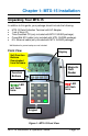

Page 1-2 MTX-15 Installation & Operation Guide
Note: The date and time in the desired format (e.g., military or
AM/PM) are downloaded from the Time & Attendance
software. The software will also control DST and any offset
(TZ). Also downloaded to the terminal for display are the
employee hours and last 4 punches.
Dip Switch
The Dip Switch on the MTX-15 PCB in most instances should
not have to be changed from the default factory setting, which
is both S1 and S2 set to ON as follows:
Switch 1: Enables the termination resistor (ON position).
When RS-485 serial communications are used and the terminal is
located at the end of the serial chain, this switch should be ON. It
should also be ON for Modem and Network terminals. For all RS-485
terminals except the last one, this switch should be OFF.
Switch 2: Disables RS-485 communications (OFF position) in order
to permit firmware upgrades via RS-232 (serial models only). For
normal operation, this switch should always be in the ON position.
Note: Firmware upgrades should never be attempted without
consulting Amano Technical Support for detailed instructions.
Data should always be polled from the Amano Time &
Attendance Software before updating the firmware on the
terminal as the current punch information at the terminal
could be lost.
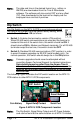
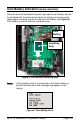
The following Figure illustrates the DIP switch location on the MTX-15
PCB relative to other MTX-15 PCB components.
Coin Battery Signal Relay Contact Serial Port
Figure 2: MTX-15 PCB Component Location
Note: The Dip Switch, Signal Relay Output and AC Power Adapter
cord can be found at the same location on all MTX-15 models.
DIP Switch
Reset Button