MTX-15 TM Data Collection Terminal Installation and Operation Guide
Thank you… For purchasing another fine product from Amano Cincinnati, Inc. Proprietary Notice This document contains proprietary information and such information may not be reproduced in whole or in part without written permission from: Amano Cincinnati, Inc. 140 Harrison Avenue Roseland, New Jersey, 07068-1239 Amano Cincinnati, Inc. reserves the right to make equipment changes and improvements that may not be reflected in this document.
Table of Contents Chapter 1: MTX-15 Installation 1-1 Unpacking Your MTX-15 ............................................................................... 1-1 Dip Switch ..................................................................................................... 1-2 Wall Mounting ............................................................................................... 1-3 Coin Battery Activation (setup retention) .......................................................
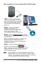
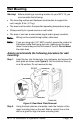
Basic Installation for Time Guardian MTX-15/A300 Package Step 1 – Unlock and remove the rear terminal back plate. Connect the MTX-15 terminal using direct connect, Ethernet, or modem cable, and host PC. Plug MTX-15 into AC power to power up. Step 2 – Install Time Guardian Software on the host PC. The installation should start automatically, but if it stalls, browse on CD to \Disk1\InstData\Windows\VM\install.
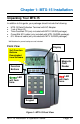
Chapter 1: MTX-15 Installation Unpacking Your MTX-15 In addition to this guide, your package should include the following: MTX-15 Data Collection Terminal with AC Adapter 1 set of Keys (2) Time Guardian CD (only included with MTX-15/A300 package). CommStik 50 ft cable (only included with MTX-15/A300 package). 6 ft. Ethernet cable (only included with MTX-15/A302 package).
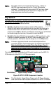
Note: The date and time in the desired format (e.g., military or AM/PM) are downloaded from the Time & Attendance software. The software will also control DST and any offset (TZ). Also downloaded to the terminal for display are the employee hours and last 4 punches. Dip Switch The Dip Switch on the MTX-15 PCB in most instances should not have to be changed from the default factory setting, which is both S1 and S2 set to ON as follows: Switch 1: Enables the termination resistor (ON position).
Wall Mounting Warning! Before selecting a mounting location for your MTX-15, you must consider the following: The mounting surface and hardware must be able to support the unit’s weight, 6 lbs. (2.7 kg). The area must be within the specified operating temperature range. Close proximity to a power source or wall outlet. The area or wall can accommodate signal and/or power conduits. Note: Wiring can be routed through either cable feed.
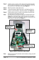
Step 3. Install a screw or anchor at the mark and hang the back plate from the top-mounting hole. Level the back plate by centering the vertical line in the bottom hole (see Figure 4). Step 4. Mark the location of the bottom hole. Step 5. If using the square Cable Feed hole in the Backing Plate for power or communications, mark this location (see Figure 4). Step 6. Install another screw or anchor for the bottom-mounting hole and secure the back plate to the wall.
Coin Battery Activation (setup retention) Once the terminal back plate has been removed the coin battery should be activated with the terminal face down, by pulling and removing the green paper insulating strip from under the coin battery (see Figure 5). This battery is used to maintain time/date setup.
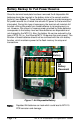
Battery Backup for Full Power Reserve Once the terminal back plate has been removed the 6 disposable AA batteries should be inserted in the battery slots in the correct position [polarity] (see Figure 7). These batteries are used to provide emergency full power reserve for a limited time should AC power to the terminal be interrupted. During this type of emergency the terminal will maintain full function utilizing the power from these batteries to let employees in or out.
Signal Relay Circuit (used to ring Bell/Buzzer) Warning! All connections to the relay contacts must be Class 2 wiring with a maximum of 24 VDC, 1A. The MTX-15 is equipped with one (1) NORMALLY OPEN (NO) relay contact that can be used to control external equipment such as a bell or buzzer. Connection to the contacts is via the screw terminal block located on the back panel PCB alongside the serial connector. The terminal block can be removed from the PCB to facilitate wiring (see Figure 8).
A typical wiring diagram for a bell circuit is shown below: Communication Connections Connections between your Host PC and MTX-15 terminal(s) are based upon the model of the MTX-15 terminal you have purchased (SerialDirect, Ethernet-network, or Modem). Serial Connection Use the CommStik™ (50 foot RJ-11 to USB) communications cable to interface with the host PC. This part comes standard with the Time Guardian MTX-15/A300 package.
Note: When there is only one RS-485 MTX-15 terminal in the system, DIP Switch 1 must be in the ON position to enable the termination resistor. Note: If the distance between the terminal and the host PC is more than 50 feet, two junction boxes will be required (see the next page), or you can use an RJ-11 coupler with a RJ-11 extension cable, not to exceed 3,950 feet. Multi-terminal (maximum of 31) applications require the DIP Switches to be OFF in all but the last terminal on the communications line.
*The maximum number of terminals is dependent upon the distance and the quality of cabling used. It is recommended that Belden Low Voltage Computer Cable, P/N 9841 or equivalent be used to connect the junction boxes for this application. Warning! Page 1-10 Please note that terminal #3 (used for the RS-485 cable Shield) is disconnected from the internal RJ-11 receptacle of the junction box. This is deliberate; the shield connection is NOT fed through to the MTX-15 Terminal.
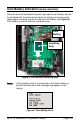
Interior View with Back Plate Removed Signal Relay Output. DIP Switch and Reset Button. RJ-11 Jack (RS-232/485) from CommStik Connected to USB-Serial Port. AC Power.
Modem Connection The dial-up modem communication is generally used when the host PC is located at a different facility from the terminal(s). This configuration can consist of a single MTX-15 Modem Terminal, or an MTX-15 Modem Terminal networked (via RS-485) with a group of up to (29) Serial MTX-15 Terminals. The Modem Terminal is connected to a standard telephone line.
Interior View with Back Plate Removed RJ-11 Jack for Serial Port (Not Used). RJ-11 Jack for Modem (Plug Phone Line In).
Ethernet Connection (Network) Network Terminals can be connected to a standard 10BaseT or 100 BaseTx computer network. In addition, each Network Terminal can have a group of up to 29 Serial Terminals networked via RS-485 (in the same manner described previously for a Modem Terminal). Note: The serial connections for the RS-485 branch network are the same as for the RS-485 wiring described previously.
Interior View with Back Plate Removed Disposeable AA Batteries for Backup Power for Display and Reader MAC Address Located Here Connect RJ-45 Jack for Ethernet Cable Here [on Digi™] Figure 11: Ethernet Connection to MTX-15 Note: Failure of the AA Batteries will not cause the loss of any transaction and setup data stored in the flash memory of the terminal, provided the coin battery is enabled (see page 1-5).
MTX-15 Startup (Initialization) Once connections have been made and the terminal back plate has been mounted on the wall, the MTX-15 terminal can be initialized. To do so perform the following: Step 1. Re-install the MTX-15 terminal on the back plate by placing the notch on the bottom of the Back Plate (see Figure 3) over the plastic tab in the bottom of the terminal cabinet. Pivot the terminal up so the locating pin on the Back Plate aligns with its corresponding hole in the cabinet.
Figure 13: Terminal Status After display of terminal status, the initial startup display will appear with January 1, 2000, 12:00 am. Also no function buttons will be displayed until the terminal is downloaded from the host. Figure 14: MTX-15 Initial Startup Display Note: The time and date cannot be set from the keypad; it must be downloaded to the terminal using the Time & Attendance software from the host PC. Pressing any numeric key will display a flashing “E04 Keypad Lock” on top.
This page intentionally left blank.
Chapter 2: MTX-15 Operation with Time & Attendance Software The MTX-15 is a data collection terminal to record the time attendance information, which is integrated with the Amano Time & Attendance software such as Time Guardian, Time Guardian Plus and Time Guardian Pro for further data processing. The MTX-15 terminal enables an employee to swipe a magnetic badge card, use a proximity reader, or enter his/her badge number and other information.
limited to 5. The host software will decide the number of hours that should be downloaded and the text label for each hour type. The user can view this information from the main screen as shown below. Lock-In Schedule: The MTX-15 supports the ability to restrict the employee to a certain time period. The schedules are configured and downloaded from the Amano Time & Attendance software.
Daily MTX-15 Use Normal Punching at the MTX-15 terminal The MTX-15 firmware supports a 12 digit badge number so the terminal button after will always expect the user to press the enter entering the badge number and it will prefix the badge number with zeroes if it is less than 12 digits. For example, if the user enters “1234” for a badge number and presses the enter will be treated as “000000001234”. button, the number Swipe badge or use the keypad to enter ID to punch.
Note: The terminal contains repunch protection. An error message, “E03 Only one” will appear if you try to punch more than one within 3 minute period. Note: All employee information such as hours, punches, and unlock schedule is always displayed at the MTX-15 terminal in military time format (i.e., 5:00PM = 17:00). However, the clock time displayed is controlled by the settings in the Amano Time & Attendance software, which can be set to either AM/PM or military.
Figure 17: View Employee Punches Step 2. Use the Function buttons (see Figure 17) as indicated underneath the display to move Up or Down to highlight “View Punches” and press enter to select and the screen will change to the following (see Figure 18). Figure 18: Enter ID for Punches Step 3. The user can swipe his/her badge magnetic card or use the to accept keypad to enter the ID number. Press enter the ID number. If a mag card is used, there is no need to press enter .
Figure 20: Scroll Down to View 4th Punch Note: The terminal will display the punch information if a valid ID is entered and it finds the ID in the employee table in the terminal. The following error message will display for invalid entry; “E00 ID NOT Found” All the punch information is not communicated in real time with the terminals from the Time & Attendance software, so the terminal will show the last 4 punches as of yesterday.
View Employee Hours at MTX-15 The user should be on the main screen to access the employee hour information. button on From the normal main display press the menu the left to view employee information choices (see Figure 21). Figure 21: View Hours at Terminal Use the Function buttons as indicated underneath the display to move Up and Down to highlight “View Hours” and press enter on the keyboard to select and the screen change to the following (see Figure 22).
Figure 23: First Page of Employee Hours at Terminal To see the 2nd page of an employee’s hours, press the Down function button.
Lock-In Schedule Feature The new MTX-15 firmware has the ability to restrict the employee to a scheduled time period. For example, depending on the schedule an employee will not able to punch before 8:00AM and after 5:00PM, Monday thru Friday.The schedules can be configured and downloaded from the host Time & Attendance software. Each employee will have his/her own schedule for each day. See the Time & Attendance Software User Guide for additional information about Schedules.
Step 2. Use the Function buttons (see Figure 25 as indicated underneath the display to move Up and Down to highlight “Unlock Schedule” and press enter on the keyboard to select. The screen will change to the following (see Figure 26). Figure 26: Swipe Supervisor Badge Step 3. A user with supervisor rights must swipe his/her badge magnetic card to unlock the terminal and the screen will change to the following (see Figure 27).
Meal Punch Procedure for MTX-15 The user should be on the main screen as shown in the example Figure to access the employee Meal punch function. The Meal button box must be checked on the Time & Attendance Terminal Options screen (see page 2-24) for this function button to be active on the MTX-15 terminal. Figure 28: MTX-15 Normal Startup Display Step 1. From the normal main display (see Figure 28) press the meal function button to enter an employee ID for a meal punch (see Figure 29).
Note: The terminal will allow the meal punch if a valid ID is entered and it finds the ID in the employee table in the terminal. The following error message will displayed for invalid entry. “E00 ID NOT Found” Note: If the ID fails the validation rule, the screen will display the following error message. “E03 ID Only One” function button or esc return to the previous menu. Step 3.
Step 2. The user can swipe his/her badge magnetic card or use the to accept keypad to enter the ID number. Press enter the ID number when using the keypad. If the ID is valid for that terminal, the screen will change to display name [if a name exists] and display the 2nd row with Coffee and Break function buttons under the first row of buttons (see Figure 33). 2nd row of function buttons will appear. Figure 33: Select Coffee or Break Function Step 3.
Step 1. From the normal main display (see Figure 34) press the function button to enter an employee ID for a transfer labor transfer (see Figure 35). Figure 35: Enter Employee ID for Transfer Step 2. The user can swipe his/her badge magnetic card or use the to accept keypad to enter the ID number. Press enter the ID number when using the keypad.
Step 4. If the function button has more than one labor level, use the function keys to move Up and Down to highlight the desired labor level. At this point use the keypad to enter the department number [4 digits maximum] to transfer to the Labor function Level (in this example Level 1). Press the Save button to save the transfer. From this screen, use the Back button to exit and return to the main display.
MTX-15 Setup with Amano Time & Attendance Software Note: Prior to commencing with the Time & Attendance software Setup Wizard, Amano recommends that you install the MTX15 terminal(s), using this MTX-15 Terminal Installation and Operation Guide. The MTX-15 terminal is installed to communicate with your PC/Time & Attendance software. You may need to obtain the IP address for each Ethernet MTX-15 terminal(s) connected to the system.
Use Step 8 if: Do you have Terminals other than Access Control Terminals? If Yes, the Time & Attendance software will automatically poll and upload punches from connected MTX-15 terminals each time the software is opened. If No, the connected MTX-15 terminals will have to be polled manually using the Communications module in the Time & Attendance software.
Do you want to configure Bell Schedules? If Yes is selected for Bell Schedules, click the Bell Schedule button for the Bell Schedules screen (see Figure 41). Figure 41: Software Setup for Bell Schedules Special Note: Selecting Holidays will only work with HandPunches (all HandPunch models). A Bell schedule requires you to enter the Duration for the bell to ring, the time of day for the bell to ring and the days of the week.
Do you want to configure your Terminals? Answer Yes to this question if you are using terminals such as a MTX-15 terminal via a serial, Ethernet, or modem connection. Direct (serial) Connection If Yes is selected, and a Direct connection using the included 50 foot USB/serial cable is desired, you can just use the “MTX-15 Default” location. You do not have to do anything else. The MTX-15 terminal, if connected, will automatically be detected upon login.
Select “MTX-15 Default” on the General tab from the dropdown menu for Locations [recommended for easy configuration]. Click on Connection tab to select Ethernet for Connection Type and enter your IP Address. The default MTX-15 Location automatically defines everything else for Ethernet. Click on button. Figure 43: Software Setup for Locations with Connections Tab A Bell Schedule (optional) and Terminal Validation list should be setup.
Step 2. In the Description field, enter a brief description of the Location. This field is optional. Step 3. In the Term Type field; select MTX-15. Step 4. In the TZ (Time Zone) Offset field, select the time zone difference (if applicable) between the physical location of your PC and the MTX-15 terminals. Step 5. In the Output Path field, enter the path of the output XML file. If necessary, press the Browse button to navigate to the location of the XML output file. Step 6.
consult Chapter 3: Network Configuration of this Guide for additional information about hardware configuration, and identifying the IP address]. Modem: A modem can be used at the Com Port of the Host PC to communicate to the terminal(s). If selected, you must select the Com Port, Baud Rate, Modem Type, and enter the Phone Number. If your modem is not available from the list, select a compatible model. This information should be provided in the modem’s documentation.
Note: The error message “ no terminals found” will appear if there is a communication problem with the terminal(s) at the location. Please check cable connection and/or configuration. The Ethernet and direct connection MTX-15 terminals in this location should appear in the Terminals list (see Figure 46) if found. Figure 46: Locations Terminal List Note: Search eyeglass function is only for MTX terminals. Step 12.
Step 13. In the Name field, enter in a unique name [required field] that will be used to describe the terminal. This field will be automatically populated with the MAC address when the eyeglass find button is used. Step 14. In the Number field, enter in a unique number for the terminal if allowed. Step 15. In the Serial No. field, a unique number will appear for a found MTX-15 terminal. Step 16. If you wish to assign a Bell Schedule to the terminal, select one from the dropdown list in the Bells field.
Note: The Coffee, Break, and Meal buttons will not be able to be selected if the Advanced Overtime Module has not been activated. This module provides the Shifts with Meal Templates (see Time & Attendance User Guide). By default the Labor button will be selectable. However, if the Labor button box is not checked the transfer button will not appear on the MTX-15 terminal display. Therefore, no labor transfer will be allowed at the terminal. Step 21.
Time & Attendance Software Communications Module With the Time & Attendance Software open on the host PC, from the tree view, click on the Communications module within the Daily Activities group and the following type of screen should appear for Time Guardian Plus. Note – the tree view can look a little different depending upon which modules are activated and/or whether it is Time Guardian Pro (all modules will be active).
To select specific terminals within a location, double-click on the desired location row, and the following Communications dialog will appear: Note: The Send fingerprint maps , Receive fingerprint maps , and Clear fingerprint maps icons will be grayed out unless an FPT-40 terminal is selected. Figure 51: Software Communications Screen Select terminals in the Terminals list by placing a check in the Select box of each terminal.
This page intentionally left blank.
Chapter 3: MTX-15 Diagnostics Running Diagnostics In addition to a power up diagnostic, the MTX-15 has an internal diagnostic utility for verifying the correct operation of the terminal, adjusting the display contrast and configuring network communications (Ethernet terminals only). To access diagnostics: Step 1. Cycle the AC power on the MTX-15 or press the Reset button on the PCB (see Figure 2). Step 2. key when the Memory Bank test first Press the enter appears.
Relay, Keypad, LED and Buzzer Test With Rely, Key, LED, Buz highlighted press enter keyboard to advance to the test screen. on the Figure 53: Relay, Keypad, LED & Buzzer Test Screen Use the Function keys to move up or down to highlight the desired test and press enter to perform that test. Keypad test: Pressing any numeric key will display the number on the Keypad test line. Pressing the esc key will display “C”, while pressing the enter key will display “E”.
Reader Test With Reader highlighted press enter on the keyboard to advance to the READER TYPE test screen (see Figure 54). This test will display the type of reader installed in the MTX-15 terminal and indicate the functional status of the reader. Figure 54: Reader Type Test Screen Swipe a badge to initiate the test.
Screen Test With Screen highlighted press enter on the keyboard to perform the screen test. This diagnostic tests the display by turning on all the pixels. Any spots would indicate a defective pixel. Press the left Function key to return to the main Diagnostic menu. Network Configuration This selection will only function on an MTX-15 Terminal with Ethernet and can be used to configure network communications.
Figure 57: IP Settings Screen Copy down the Address, Subnet, and Gateway IP settings displayed in order to configure your Time Guardian time and attendance software. Press the left function key or esc maintain the automatic setting. Note: key to exit the screen to It is important to exit this screen without saving. If save is pressed, the terminal will reboot with the displayed address in manual mode (see below); automatic IP setting will be disabled.
Invalid Network Settings If you set the IP Address manually with the wrong IP Address, Subnet Mask, and/or Gateway Address one of the following error messages may be displayed; ERROR Invalid IP Address, Invalid subnet mask, Invalid gateway address, or Invalid network configuration (no route from host to gateway) Press enter to reboot the terminal and clear the error message. You may need to obtain the appropriate IP settings from your network administrator.
Specifications Operating Environment: 32°F to 113°F (0°C to 45°C) 10 - 90% relative humidity, non-condensing AC Adapter Power Input: 105 - 130 VAC, 50-60 Hz Power Consumption: 1.5 Watts (Serial version) 2.1 Watts (Modem version) 3.0 Watts (Network version) Dimensions: 8.86" L X 5.5" W X 1.9" D (225 mm L X 140 mm W X 49 mm D) Weight: 6 lbs. (2.7 kg) Daylight Saving Time (DST): Settings are programmable through Amano Time & Attendance software. Employee Badges: 3.375" L X 2.215" W X 0.
Battery Backup Time (Range dependant on reader type) Serial Version: 14 to 24 hours Modem Version: 7 to 10 hours Ethernet Version: 5 to 6 hours Display: 2.8” diagonal, 128 x 64 dots resolution LCD reflective (no backlight) Keypad: 3x4 keypad (0~9, ENT, ESC) + 4 function keys (used for Cost Center /Job costing feature).
www.amano.com/time AMX-407600 ● Copyright © 2010 Amano Cincinnati, Inc. ● Printed in U.S.A.