
Owner's Manual

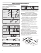


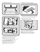


Table Of Contents

10
12. Make electrical connection
Option 1 - Direct Wire Installations
■ Use a UL listed/CSA approved wire connector
andconnectthe 3 white wires (A) together.
■ Use a UL listed/CSA approved wire connector
andconnectthe 2 black wires (B) together.
■ Connect the green (or bare) ground wire (C) from the
powersupply to the green ground screw in the electrical
boxand tighten the screw securely.
Reinstall the electrical box cover.
Reconnect power.
Option 2 - Power Cord Kit Installations
For optional power cord kit installations, follow the instructions
supplied with the power cord kit. See the “Assistance or
Service” section for information on ordering.
NOTE: Use only with range hood cord connection kits that
havebeen investigated and found acceptable for use with
thismodel range hood.
13. Complete the installation
■ Install a 120 V, 75 W maximum, light bulb with
E26 base.See “Replacing the Light Bulb”in
the“RangeHoodCare”section.
■ If removed previously, replace the lter. See “Metal or
Charcoal GreaseFilter” in the “Range Hood Care” section.
For vented installations: Install a metal lter.
For non-vented (recirculating) installations: Install
acharcoallter.
■ Check the operation of the range hood fan and light.
Seethe“Range Hood Use” section.
If the range hood does not operate, check to see whether
acircuit breaker has tripped or a household fuse has blown.
Disconnect the power and check the wiring connections.
NOTE: To get the most efcient use from your new
rangehood,read the “Range Hood Use” section.
RANGE HOOD USE
The range hood is designed to remove smoke, cooking
vapors,and odors from the cooktop area. For best results,
startthe hood before cooking and allow it to operate several
minutes after the cooking is complete to clear all smoke and
odors from the kitchen.
The hood controls are located on the front panel of
therangehood.
Range Hood Controls
Operating the light
Press the light switch to the left to turn the light On.
Press the light switch to the right to turn the light Off.
IMPORTANT: Flicker and visual uctuation can be present every
time the lamp switch is activated. The duration of the icker will
depend on the manner and velocity that the light switch changes
position.
Operating the fan
The fan has 2 speeds.
Press the fan switch to the left for Low speed.
Press the fan switch to the right for High speed.
Return the fan switch to the center to turn the fan Off.
A
B
C
WARNING
Fire Hazard
Electrically ground the blower.
Use copper wire.
Connect ground wire to green ground screw in
terminal box.
Failure to do so can result in death, fire, or
electrical shock.
A
C
B
A. Light housing and cover
B. Grease lter retainer
C. Grease lter
A
B
Off
On
Low
Off
High
A. On/Off light switch
B. Fan speed switch