Technical Information Model and Manufacturing numbers listed on page 3. 40" 80% Gas Furnaces GUIC, GCIC • Refer to Service Manual RS6600001 Rev. 1 for installation, operation, and troubleshooting information. • All safety information must be followed as provided in the Service Manual. • Refer to the appropriate Parts Catalog for part number information. D E SI G N This manual replaces RT6621003 Rev. 0 April 2000. CE RT I F I E D CE REV.
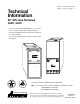
PRODUCT IDENTIFICATION The model and manufacturing number are used for positive identification of component parts used in manufacturing. When engineering and manufacturing changes take place where interchangeability of components are affected, the manufacturing number will change. It is very important to use the model and manufacturing numbers at all times when requesting service or parts information. G U I C 045 C A 50 Product Type Airflow Capability 30: 3.0 Tons G: Gas Furnace 40: 4.0 Tons 50: 5.
PRODUCT IDENTIFICATION The model and manufacturing number are used for positive identification of component parts used in manufacturing. When engineering and manufacturing changes take place where interchangeability of components are affected, the manufacturing number will change. It is very important to use the model and manufacturing numbers at all times when requesting service or parts information.
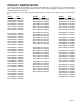
PRODUCT DIMENSIONS GUIC 80% Upflow/Horizontal Upflow Left Side View Upflow Front View 28-3/4 28 20 3/4 Supply A Knock-Out For Venting E 3/4 B C 3/4 4 5/8 Upflow Right Side View Electrical Hole "High Voltage" 4 11/16 Electrical Hole "Low Voltage" Supply Gas Supply Hole 14 31 34-5/8 23 28-1/4 1 1/2 31-5/8 4-5/8 37-3/8 40 2-1/2 Side Cut-Out Side Cut-Out 1 5/8 1 23 1/2 Bottom Knock-Out D Bottom Knock-Out GUIC DIMENSIONS FURNACE MODEL A B C D E Minimum Vent Diameter GUIC0
PRODUCT DIMENSIONS GCIC 80% Counterflow/Horizontal COUNTERFLOW FRONT VIEW A 3/4 COUNTERFLOW RIGHT SIDE VIEW COUNTERFLOW LEFT SIDE VIEW 28 3/4 B 3/4 28 20 1/8 3/4 3" 4 3/4 22 28 1/4 4 5/8 31 5/8 34 5/8 KNOCK-OUT FOR HORIZONTAL VENTING 40 31 GAS SUPPLY HOLE A Raytheo n C ompany SUPPLY ELECTRICAL HOLE "LOW VOLTAGE" 18 5/8 UNFOLDED FLANGES 20 1/8 FOLDED FLANGES D UNFOLDED FLANGES E FOLDED FLANGES SUPPLY ELECTRICAL HOLE "HIGH VOLTAGE" 1 3/4 2 1/2 Units are shipped with unfolded bottom fla
PRODUCT DESIGN General Operation This GUIC/GCIC furnace is equipped with an electronic ignition device to light the burners and an induced draft blower to exhaust combustion products. Accessibility Clearances (Minimum) MINIMUM CLEARANCES TO COMBUSTIBLE MATERIALS (INCHES) UPFLOW An interlock switch prevents furnace operation if the blower door is not in place. Keep the blower access doors in place except for inspection and maintenance.
PRODUCT DESIGN PRESSURE SWITCH TRIP POINTS AND USAGE CHART MODEL GCIC GUIC MINIMUM NEGATIVE PRESSURE WITH FLUE NOT FIRING TYPICAL SEA LEVEL DATA MINIMUM NEGATIVE PRESSURE WITH FLUE FIRING TYPICAL SEA LEVEL DATA TRIP POINT PRESSURE SWITCH (Prod.) LABEL COLOR TRIP POINT HIGH ALTITUDE KIT LABEL COLOR TRIP POINT HIGH ALTITUDE KIT LABEL COLOR -0.85 -0.60 -0.55 10727920 DK BLUE -0.50 HAC1PS11 10727915 LT BLUE -0.
PRODUCT DESIGN ROLLOUT LIMIT SWITCHES 10123508 10123509 10123510 10123511 10123512 10123513 Part Number or or or or or or 10123527 10123528 10123529 10123530 10123531 10123532 Open Setting °F 260 275 300 250 325 350 BROWN PINK GREEN LT BLUE LT PURPLE GRAY Color GUIC045**30 1 GUIC070**30/40 1 GUIC090**30/50 1 GUIC115**40/50 1 GUIC140**50 1 GCIC045**30 GCIC070**30 1 1 GCIC070**40 1 GCIC090**30/50 1 GCIC115**40/50 1 GCIC140**50 1 AUXILIARY LIMIT SWITCHES 10123506 Part Number or 10123525 8
PRODUCT DESIGN Coil Matches: A large array of Amana coils are available for use with the GUIC and GCIC furnaces, in either upflow, counterflow, or horizontal applications. These coils are available in both cased and uncased models, with or without a TXV expansion device. These 80% furnaces match up with the existing Amana coils as shown in the chart below.
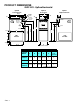
FURNACE SPECIFICATIONS MODEL GUIC045CA30 GUIC045CX30 GUIC045DA30 GUIC045DX30 GUIC070CA30 GUIC070CX30 GUIC070DA30 GUIC070DX30 GUIC070CA40 GUIC070CX40 GUIC070DA40 GUIC070DX40 GUIC090CA30 GUIC090CX30 GUIC090DA30 GUIC090DX30 GUIC115CA50 GUIC090CA50 GUIC140CA50 GUIC115CA40 GUIC115CX50 GUIC090CX50 GUIC140CX50 GUIC115CX40 GUIC115DA50 GUIC090DA50 GUIC140DA50 GUIC115DA40 GUIC115DX50 GUIC090DX50 Btuh Input (US) 46,000 69,000 69,000 92,000 92,000 115,000 115,000 140,000 Output (US) 36,800 55,200 55,2
FURNACE SPECIFICATIONS MODEL GUIC070DA40 GUIC070DX40 GCIC070DX40 Btuh Input (US) 69,000 69,000 69,000 Output (US) 55,200 55,200 55,200 80% 80% 80% Rated External Static (" w.c.) A.F.U.E. .12 - .50 .12 - .50 .12 - .50 Temperature Rise (°F) 35 - 65 35 - 65 45 - 75 Pressure Switch Trip Point (" w.c.) -0.55 -0.55 -0.55 Blower Wheel (D" x W") 10 x 8 10 x 8 10 x 8 Blower Horsepower 1/2 1/2 1/2 Blower Speeds 4 4 4 Max CFM @ 0.5 E.S.P.
FURNACE SPECIFICATIONS MODEL GCIC045CX30 GCIC070CX30 GCIC070CX40 GCIC090CX30 GCIC090CX50 GCIC115CX40 GCIC115CX50 GCIC140CX50 Btuh Input (US) 46,000 69,000 69,000 92,000 92,000 115,000 115,000 140,000 Output (US) 36,800 55,200 55,200 73,600 73,600 92,000 92,000 110,400 80% 80% 80% 80% 80% 80% 80% 80% Rated External Static (" w.c.) A.F.U.E. .10 - .50 .12 - .50 .12 - .50 .15 - .50 .15 - .50 .20 - .50 .20 - .50 .20 - .
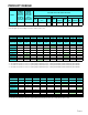
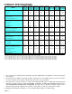
BLOWER PERFORMANCE SPECIFICATIONS GUIC Blower Performance (CFM & Temperature Rise vs. External Static Pressure) ( External Static Pressure (Inches Water Column) TONS AC Model ) Heating Speed As Shipped MOTOR SPEED 0.1 @ 0.5" 0.2 0.3 0.4 0.5 ESP CFM Rise CFM Rise CFM Rise CFM Rise CFM 0.6 Rise CFM Rise HIGH 3.0 1460 --- 1400 --- 1345 --- 1280 --- 1200 --- 1110 --- GUIC045**30 MED 2.5 1200 --- 1150 --- 1100 --- 1050 --- 980 35 900 38 (Low) MED-LO 2.
BLOWER PERFORMANCE SPECIFICATIONS GCIC Blower Performance (CFM & Temperature Rise vs. External Static Pressure) ( External Static Pressure (Inches Water Column) TONS AC Model ) Heating Speed As Shipped MOTOR SPEED 0.1 @ 0.5" ESP CFM 0.2 Rise CFM 0.3 Rise CFM 0.4 Rise CFM 0.5 Rise CFM 0.6 Rise CFM Rise HIGH 3.0 1455 --- 1430 --- 1360 --- 1255 --- 1160 --- 1040 --- GCIC045**30 MED 2.5 1255 --- 1200 --- 1150 --- 1075 --- 990 --- 890 38 (Low) MED-LO 2.
BLOWER PERFORMANCE SPECIFICATIONS GUIC/GCIC070**40 Blower Performance (CFM & Temperature Rise vs. External Static Pressure) TONS AC External Static Pressure (Inches Water Column) Model ( ) Heating Speed As Shipped MOTOR SPEED 0.1 @ 0.5" 0.2 0.3 0.4 0.5 0.6 ESP CFM Rise CFM Rise CFM Rise CFM Rise CFM Rise CFM HIGH 4.0 1799 --- 1742 --- 1694 --- 1622 --- 1529 --- 1444 GUIC070**40 MED 3.5 1730 --- 1590 --- 1542 --- 1483 --- 1404 36 1330 (Med-Lo) MED-LO 2.
BLOWER PERFORMANCE SPECIFICATIONS 16 Rev. 1 BTU OUTPUT vs TEMPERATURE RISE CHART 100 600 CFM 90 700 80 800 TEMPERATURE RISE 900 1000 70 1100 1200 60 1400 1600 50 1800 2000 2200 2400 CFM 40 30 FORMULAS BTU OUTPUT = CFM x 1.08 x RISE BTU OUTPUT RISE = ÷ CFM 1.
R 6 GAS VALVE (GV) PRIMARY ROLLOUT LIMIT (RL) CONTROL M G C 1 BR BR CAPACITOR (CAP) TERMINAL ORDER REARRANGED FOR CLARITY 3 DOOR SWITCH (CLOSED WHEN DOOR IN PLACE) GND L1 IGNITOR N 115V FIELD CONNECT WARNING:DISCONNECT POWER BEFORE SERVICING.WIRING TO UNIT MUST BE PROPERLY POLARIZED AND GROUNDED.
R G PRIMARY ROLLOUT LIMIT (RL) 6 CONTROL GAS VALVE (GV) 2 P 3 * P GI N R R A NI RE GF NN E 0 0 K UN P DD U 1 2 BR-21 12 9 6 HLO BK-6 FP COMBUSTION BLOWER WH (CB) GV TH VT-55 RO1 6 GN BK TR C NC RD-22 GND HLI BU-36 FS L E AN MS EO R RD -22 WH-23 MV WH-33 FLAME SENSOR L I M I T NEUTRAL 120VAC BU-15 RO2 PS VT -55 YL-11 LIMIT MV PRIMARY LIMIT CONTROL BU25 NO C L X E H I I F A U R N M C M E R NO PS PRESSURE SWITCH (PS) NC OR16 CONTROL I I NG DN GUIC and GCIC
PRIMARY ROLLOUT LIMIT (RL) 6 CONTROL RD44 TERMINAL ORDER REARRANGED FOR CLARITY P GI NR R AN I RE GF N N E 0 0 KU NP D DU1 2 9 6 3 BK-6 11 8 5 2 10 7 4 1 GN THERMOSTAT CONNECTIONS WH HLO FP COMBUSTION BLOWER (CB) 12 VT-55 BK GV TH 6 GN RO1 C NC RD-22 TR BU-36 FS LE AN MS EO R RD -22 WH-23 MV GND HLI WH-33 FLAME SENSOR L I M I T PS VT -55 BU-15 RO2 NO PS YL-11 LIMIT MV 24 V PRIMARY LIMIT CONTROL NEUTRAL 120VAC FORMER BU25 NO C L X E H I I F A U R N M
WARNING:DISCONNECT POWER BEFORE SERVICING. WIRING TO UNIT MUST BE PROPERLY POLARIZED AND GROUNDED.
GUIC and GCIC WR50A50 INTEGRATED IGNITION CONTROL This schematic is for reference only. Not all wiring is as shown above, ! WARNING LINE NEU 120 VAC LINE HOT IGNN IGN K6 GND GAS VALVE. MV K7 MV K8 PS HUM NEU HLO K5b HUM K4 IND AUX LIMIT. INDUCER PRESSURE. SWITCH HIGH. LIMIT. HUMIDIFIER TO AVOID POSSIBLE ELECTRICAL SHOCK, PERSONAL INJURY, OR DEATH, DISCONNECT THE POWER BEFORE SERVICING. IGNITOR FLAME SENSOR PROBE FP 3M 1M .001 K1a K1b K2a CIR HEAT. COOL. PARK. PARK.
Rev. 1 GUIC and GCIC WR50A55 INTEGRATED IGNITION CONTROL This schematic is for reference only. Not all wiring is as shown above, refer to the appropriate wiring diagram for the unit being serviced. ! WARNING LINE NEU 120 VAC LINE HOT IGN IGNITOR FP 3M .