STREAK 800 HEXACOPTER Instruction Manual 1
Contents 1. Introduction.........................................................................................................................................................3 2. Safety Notes........................................................................................................................................................5 3. Equipment Required For Assembly....................................................................................................................6 4.
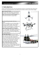
1. Introduction Alware's Streak 800 Hexacopter is the next generation aircraft for professional aerial filming with big Cameras, long flying time FPV, search and rescue activities in the air with minimum budget. Quick Collapsible Design: Unlike other huge multicopters, Streak 800 has an extremely convenient collapsible structure design. Four arms can be folded together within 1 min without using any tools. This greatly reduce the effort used in transportation.
Large Current Power/ESC Board: Streak 800 comes with a large current distribution board. The whole board as a conductor, it support up to 100A input which is a lot more enough for Steak 800. It distributes a power imput to six speed controllers within the board in a clear way. This does not produce magnetic thus less influence to sensors. High Efficient APC Propellers: Streak 800 comes with 3 pairs of Genuine APC Composite 14x4.7 Propellers.
2. Safety Notes Do fly only in safe areas and always away from other people! Do not operate RC aircraft within the vicinity of homes or crowds of people. RC machine are prone to accidents, failures, and crashes due to a variety of reasons including pilot error, radio interference, and lack of maintenance. Pilot are responsible for their actions and damage or injury occuring during the operation of RC aircraft machine.
3. Equipment Required For Assembly 6pcs-- 40A ESC(6S 18pcs-- 3.5mm Bullet 1pcs-- “+” Mode 22.2V) (e.g. HobbyWing Connector (Female) for Hexacopter Controller FlyFun 40A ESC) 6pcs ESC 2pcs-- 6S LiPo Battery 4500-7500mAh 22.2V ( Will be connect in Parallel) 2pair-- Connectors For Batteries and Power Board 1pcs-- Lipo Charger & the connector to fit the Lipo Battery.
4. Check List Please Check the Follow parts. Alware Multicopter Brushless Motor 3515-15 KV400 (ALS800KIT not include.) 6 Pack Screw set come with Motor. Apc Propeller 14x4.7SFP (CW) 3 Pcs Apc Propeller 14x4.7SFP (CCW) 3 Pcs Large Current Power/ESC Board with Servo Extension Wire ( 15cm ) 6 pcs 6 Set 2 pairs Battery Cable.
AWG wire Black ( 33cm ) 6 pcs AWG wire Red ( 33cm ) 6 pcs Frame parts.
Other parts : 4pcs x Hex Cap Screw M3x8mm 16pcs x Round Cap Screw M3x6mm 4pcs x Hex Cap Screw M3x16mm 24pcs x 3mm Washers 8pcs x Nylon Washer 3x7x6mm 8pcs x Battery Support Damper 1pcs x Direction Indicating Sticker 9
5. Soldering Job Solder 2 pairs Battery Cable to the Large Current Power/ESC Board and connect the other end to the Battery Connectors. (Red = +ve , Black = -ve) Do not short circuit two polarities! 1.) Solder Black and Red AWG wires to the ESC. 2.)Solder 3pcs 3.5mm Bullet Connectors (Female) to the ESC. 3.)Connect Servo Extension Wire to the Signal Connector of ESC and secure it using Adhesive Tape.
6.0 Assembly Steps - Quick Collapsible Illustration With the Quick Collapsible Design, you can fold four arms of Streak 800 easily for easy transportation and storage. However you must follow the coming step by step to fold the arms correctly, otherwise the Quick Lock Key may damage! Step 1a. Facing to the Bottom Side of the Streak 800 Body. Indicate the Forward Direction and corresponding Arm “A”, Arm “B”, Arm “C” and Arm “D” position. Only those four Arms will be foldable. Step 1b.
Step 1d. Holding one Fixed Arm and use the Thumb to push the Quick Lock Key into the Collar of Streak 800 Body. Step 1e. Repeat Step 1a to 1d to fold Arm “C”, Arm “D”. Now Streak 800 is in the Flight Position. Steps sequence to convert Streak 800 from the Flight Position to Storage Position. (**Quick Lock Key must released first before folding the Arms to prevent damage to the frame.) Step 2a. Holding one Fixed Arm and use the Index Finger to release the Quick Lock Key from the Collar of Streak 800 Body.
6.1 Assembly Steps - Flight direction indicator Step 1. Cut the Direction Indicating Sticker with a width of around 100mm. Step 2. Tear the cover layer of the Sticker before stick to the front Carbon Arm Boom. Step 3. Stick the Direction Indicating Sticker (100mm Width) to the Fixed Carbon Arm Boom as to indicate the Forward Flying Direction. Step 4. Use three pieces of Adhesive Tape to secure the Direction Indicating Sticker. Complete Flight direction indicator installation.
6.2 Assembly Steps – Motor Step 1. You will received 6 motors in ALS800-CB. Step 2. For new motors, Thread Lock must be applied to the two M3 Set Screws which is pre-inserted in the motor. (This is a must for safety flying.) Step 3. Install the Porp Mount to the motor using 3pcs M3 Hex Cap Screw. (Apply little amount of Thread Locker when assembly metal to metal parts.) Step 4. Double check the prop mount which must be installed to the motor securely.
6.3 Assembly Steps – Motor Mount Step 1. Loosen the screws before insert the motor mount to the Carbon Arm Boom. Step 2. Insert the Motor Mount to the boom and stop until the boom edge is touching the Inner Motor Metal Mount surface. Step 3. Adjust the Motor Mount to parallel to the Streak 800 body before tighten the screws. Step 4. Secure the Motor Mount by tighten the screws on the Metal Mount. Repeat Step 1 to 4 to install other Motor Mounts to the Carbon Boom Arms.
6.4 Assembly Steps – Gimbal Mounting Step 1. Uninstall the System Platform Frame. Step 2. Uninstall the Up Gimbal Mounting Frame before install the Gimbal to Streak 800. (Skip this step if you do not have Gimbal.) Step 3. Prepare 4pcs M3x16mm screws and 6pcs Nylon Washer when installing STO S-903(3axis) Gimbal or STO Camera Mount Kit S-550 STO S-903(3-axis) Gimbal mounting position. STO Camera Mount Kit S-550 mounting position.
Step 4. Install the Up Gimbal Mounting Frame back into the Streak 800 Body with 5pcs Screws. Remarks: an 1.5mm fiber washer is needed to the center screw. Step 5. Up Gimbal Mounting Frame installed back into the Streak 800 Body. Now you can move to next page -- 6.5 Assembly Steps – ESC and ESC board.
6.5 Assembly Steps – ESC and ESC board. Step 1. Prepare the Power/ESC Board with connectors soldered. (Refer to Soldering Job shown above for more details.) Step 2. Prepare 6pcs ESC with connectors soldered. (Refer to Soldering Job shown above for more details.) Step 3. Insert the Battery Power Cable and Signal Wire of the ESC into the Carbon Boom Arm. Step 4. Pick up the Battery Power Cable and Signal Wire of the ESC through the specific hole of Upper Main Frame.
Step 5. Insert the ESC into the Motor Mount completely. Repeat above steps to install the other five ESCs. Step 6. Install ESC Board onto the Nylon Rods on the Streak 800 body with 4pcs M3x6mm Round Cap Screws. Step 7. Solder Battery Power Wire of ESC to the ESC Board. (Red wire = +ve , Black wire = -ve) Step 8. Repeat Step 7 for other five ESCs. Step 9. Install the System Platform Frame back to the Streak 800 body. Step 10.
6.6 Assembly Steps – Motors & Propellers. Step 1. Prepare 4pcs M3x8mm HexCap Screws with 4pcs 3mm Washers to install the motors to the Motor Mounts. Step 2. Insert a M3x8mm Screw into a 3mm Washer then insert to the motor mount slot as to mount the Motor to it. (Apply little amount of Thread Locker when assembly metal to metal parts.) Step 3. Secure the motor to the motor mount with 4pcs screws and washers. Step 4. Insert the Motor Wires into the slot of motor mount and connect with motors.
Step 5. Repeat Step 1 to 4 for other 5 motors. Test the motor first without propellers as to ensure the rotating direction is correct. Exchange any two motor wires to the ESC as to reverse the direction if needed. Step 6. After ensuring the motors are running in the correct direction, prepare the APC Props and Prop mounting screw and washer from the motors. Step 7. Insert the Root Hole Adapter (with 6mm inner diameter) to the bottom side of APC Prop. Step 8.
6.7 Assembly Steps – Bipod Landing Gear. Step 1. Insert the Landing Gear Skid into the mounting hole of Carbon Fiber Leading Gear Assembly. (Tips: You can rotate the Landing Gear Skid into the hole with less effort.) Step 2. Adjust the length of the Landing Gear Skid. Each side of the Landing Gear Skid should be about 195mm. Step 3. Secure Landing Gear Skid onto the Carbon Fiber Leading Gear Assembly using the M3 Set Screw which is pre-installed on the Landing Gear Skid Metal Mount. Step 4.
Step 5. Correct two Bipod Landing Gear Assemblies. Step 6. Loosen the screws of the Body Landing Gear Mount. Step 7. Insert the Carbon Boom of Bipod Landing Gear Assembly into the metal mount of Body Landing Gear Mount. Step 8. Insert the Carbon Boom into the Metal Mount with the depth of approximately 5mm. Step 8. Adjust the Bipod Landing Gear Assembly to make the Landing Gear Skid be parallel to the Fixed Arm. Step 9.
6.8 Assembly Steps – Multicopter Controller Mounting Illustration. Step 1. DJI NAZA Controller Mounting illustration. (This is for reference only.) Step 2. Install System Platform Protection Frame to the Streak 800 Up Main Frame using 4pcs M3x12mm Screws and 4pcs Nylon Washers. Step 3. The logo “AL” on the System Platform Protection Frame indicating the Forward Flight Direction. Step 4. Close View.
8. Specification Kit: -Diagonal Wheelbase: 800mm -Carbon Arm Boom Length: 281mm -Carbon Arm Boom Weight: 23.
Speed Controller/ ESC: -Current: 40A or Above -Voltage: 22.2V 6S LiPo -Largest Dimension: 30x80x25mm (WxLxH) -Recommended ESC: HobbyWing 40A ESC(for 22.2V 6S Lipo) Flying Parameters: -Max. Takeoff Weight: 7.0Kg -Max. PayLoad Weight: 2.3Kg (With 12600mAh Lipo-1.7Kg) -Power Battery: 9000-15000mAh 22.2V 6S LiPo (Minimum 15C) -Hover Power Consumption: 1300W (Takeoff Weight 6.5Kg) -Max. Hover Time: 15 min (With 12600 mAh & 6.