Lensman-X Camera 3-Axis Gimbal Instruction Manual V1.
Contents 1. Disclaimer & Warning............................................................................................................3 2. Check List...............................................................................................................................4 3. Equipment Required For 360 Panning Operation...................................................................6 4. Assembly Steps – Gimbal......................................................................................
1. Disclaimer & Warning Thank you for purchasing this Alware product. Please visit our website www.alwarerc.com regularly for update information. Any technical updates and manual corrections will be available on the web page of specific product. Due to unexpected changes or upgrades, the information contained in this manual is subject to change without notice. Please strictly follow the manual to assemble and use the Lensman-X Camera 3-Axis Gimbal.
2. Check List Please Check the Follow parts. Tilt-Roll Assembly 1 Pcs Pan Axis Assembly 1 Pcs Boom Connection Assembly 1 Pcs Tripod Landing Gear Assembly 3 pcs Damping System (For Streak 800Pro) 2 pcs (Included with ALLENSXA800 only.) Damping System Screw Set (For Strek 800Pro) 4 Sets (Included with ALLENSXA800 only.) O-ring Damping System (For DJI S800) 1 Set (Included with ALLENSXDJI only.) Carbon Fiber Battery Mount For DJI S800 (Included with ALLENSXDJI only.
3. Equipment Required For 360 Panning Operation 2-Axis Gimbal Stabilizer System 1 Pcs (e.g. ZYX-GS Gimbal Stabilization System) Transmitter (2CH or above) 1 Pcs UBEC (Output 4.8-6V, 5A or 3S 11.
4. Assembly Steps – Gimbal Step 1. Loosen two M3x6mm Screw from the Pan Axis Assembly for the installation of next step. Step 2. Insert the Boom Connection Assembly into the Pan Axis Assembly. Step 3. Adjust the position of the Boom Connetion Assembly and secure with 2pcs M3x6mm Screws. (Apply little amount of Thread Locker when assembly metal to metal parts.) Step 4. Secure the Boom Connection Assembly onto the Pan Axis Assembly completely using 2pcs M3x18 Screws.
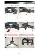
Step 7. Step 8. Insert the Tilt-Roll Assembly into the Boom Adjust the position of the Tilt-RollConnection Assembly. Assembly and seucre it with a M3x6mm Screw. (Apply little amount of Thread Locker when assembly metal to metal parts.) Step 9. Secure the Tilt-Roll Assembly onto the Boom Connection Assembly completely using 2pcs M3x20mm Screws. (Apply little amount of Thread Locker when assembly metal to metal parts.) Step 10. Prepare the Tripod Landing Gear Assembly. Step 11.
Step 13. Step 14. Secure the Tripod Landing Gear Assembly Repeat step 11-13 to install the other two using 2pcs M3x18mm Screws. (Apply little Tripod Landing Gear Assembly. amount of Thread Locker when assembly metal to metal parts.
5.0 Assembly Steps – Mounting onto Streak 800Pro Step 1. Prepare the Damping System (For Streak 800Pro). Step 2. Notice the mounting holes on the XMounting Frame which will be connected to the Damping System. Step 3. Notice the mounting holes on the Streak 800Pro buttom Main Frame to mount the Damping System. Step 4. Install the Damping System onto Strealk 800Pro using 2pcs M3x30mm Screws with 3x5x20mm Collars. Step 5. Repeat step 4 to install the other Damping System onto Strealk 800Pro. Step 6.
Step 7. Close view of step 6. Step 8. Lensman-X is now installed with Streak 800Pro.
5.1 Assembly Steps – Mounting onto DJI S800 Step 1. Prepare the O-ring Damping System (For DJI S800). Step 2. Prepare the DJI S800 H-Frame for installation. Step 3. Insert the center rod of DJI S800 H-Frame into the center 12mm Metal Mount. (Apply little amount of Thread Locker to the screws before installation.) Step 4. Loosen the 12mm Metal Mount on O-ring Damping System. Step 5. Insert the side parts of DJI S800 H-Frame into the four 12mm Metal Mounts onto the O-ring Damping System. Step 6.
Step 7. Notice the mounting holes on the O-ring Damping System which will be connected X-Mounting Frame. Step 8. Notice the mounting holes on the XMounting Frame which will be connected to the O-ring Damping System. Step 9. Step 10. Install the O-ring Damping System to the X- Close view of step 9. Mounting Frame using 8pcs M3x 10mm Screws. (Apply little amount of Thread Locker to the screws before installation.) Step 11. Top view of complete assembly.
5.2 Assembly Steps – Carbon Battery Mount For DJI S800 Step 1. Prepare the Carbon Fiber Battery Mount For DJI S800, 6pcs M2.5x18mm Screws and 6pcs 9mm Nylon Collar. Step 2. Remove 6pcs M2.5 screws from your DJI S800 Main frame as to install the Carbon Battery Mount. All accessaries and cable should be put away from the upper main frame of DJI S800. Step 3. Place 3pcs 9mm Nylon Collar onto the main frame of DJI 800. Step 4. Secure each Carbon Battery Mount using 3pcs M2.5x18mm Screws. Step 5.
5.3 Assembly Steps – Mounting onto Streak 1000 Step 1. Prepare the O-ring Damping System (For Streak 1000). Step 2. Prepare your Streak 1000 Octocopter with Landing Gear reomved. Step 3. Disassembly the FPV & GPS Mount from the Streak 1000 as to install the O-ring Damping System. Step 4. Streak 1000 with FPV & GPS Mount removed. Step 5. Step 6. Notice the holes on the Streak 1000 to install Remove 2pcs M3x10mm Screws from the Othe O-ring Damping System. ring Damper.
Step 7. Step 8. Install the O-ring Damping System onto the Back view of the O-ring Damping System. Lower Main Frame of Streak 1000 using 2pcs M3x10mm Screws and Self-Lock Nuts. Step 9. Step 10. Repeat step 6-8 to install the rest of Damping Notice the mounting holes on the O-ring System. Damping System which will be connected with X-Mounting Frame. Step 11. Notice the mounting holes on the XMounting Frame which will be connected with the O-ring System. Step 12.
Step 13. Side view of Lensman-X Gimbal installed with Streak 1000. Step 14. Install the FPV & GPS Mount back to Streak 1000 Main Frame. Step 15. Close view of step 14. Step 16. Complete installation of Lensman-X with Streak 1000.
5.4 Assembly Steps – O-Ring Damping System Step 1. Part list of each O-ring Damping System. Step 2. Default 4pcs O-ring have been used. It is able to support Camera with Appro. 1kg. You can adjust the number of O-ring used to suit your own camera. Step 3. Step 4. (Apply little amount of Thread Locker to the screws before installation.) Step 5. Step 6.
6. Electronic Installation Step 1. Prepare your own 2-Axis Gimbal Stabilizer. (We use ZYX-GS Gimbal Stabilizer as an example here.) Step 2. Stick the IMU sensor on the bottom of Camera Mount Frame with double side foam tape. Please follow the installation direction of the IMU according to factory's instruction. Step 3. Step 4. Connection of ZYX-GS Gimbal Stabilizer: Mounting illustration for the Receiver, ZYXMODE --> Receiver (GEAR) GS unit using double side foam tape.
7. Camera CG Adjustment Step 1. Remove 3pcs Screws from the Tilt Servo. Step 2. Close view of step1. Step 3. Step 4. Rotate the Tilt Servo downward to disconnect Remove 3pcs Screws from the Roll Servo. the servo gear away from the main gear. So the Tilt Axis can be move freely now for the CG adjustment with your camera. Step 5. Close view of step 4. Step 6. Rotate the Roll Servo downward to disconnect the servo gear away from the main gear.
ZYX-GS Gimbal Stabilizer Setting for Lensman-X Gimbal + Canon 60D (Appro. 1.2kg) (This is for reference only, you will need to adjust the Gain values to suit your own operation.
Step 7. Step 8. 1/4 x 13mm Camera Screw on the Camera Install your Camera onto the Camera Stand Stand Frame is used to secure standard DSLR Frame using the 1/4x13mm Camera Screw. Cameras. Step 8. Back view. Step 9. Adjust the CG for Tilt Axis by adjusting the position of the camera on the Camera Stand Frame. Step 10. Step 11. Adjust the CG for the Roll Axis by adjusting Adjust the CG for Pan Axis by adjusting the the position of the whole Camera Mount position of the whole Lower Gimbal Part. Assembly.
Step 12. Re-install the Tilt Servo back to original position and secure with the M3 Screws and Nuts. Step 13. Ensure the Tilt Servo gear is fully contact with Tilt Main gear without any gap between the gears for stable operation. CG Adjustment Completed (Adjust the CG again once you have change the camera or lens for better and stable operation.) Step 14. Re-install the Roll Servo back to original position and secure with the M3 Screws and Nuts.
8. Specifications - Made of 3K carbon fiber frames + 3K carbon boom + CNC anodized Aluminum metal parts - Pan axis control: ±360° continuous rotation (including the landing gear) - Tilt axis control: ±90° - Roll axis control: ±45° - Work with 3 Digital Metal Gear Standard Size Gimbal Servos - Working Voltage: 4.8-6V - Max. Working Current: 6A - High quality damping system included. - Total Weight: 1220g - This version is used for Streak 800Pro Hexacopter only.
End of Manual Page 24